Stuart,
Thats amazing! Hopefully you will post all the details about this version so any of us can build one.......
Am heading to work to use the vert. mill and drill press to mount the new boards to the sink... watch for photos later today! I am going to stack the main board on top and the driver board to conserve space with the main board on top of 1" standoffs. This will allow me to mount the output devices in one long row near the bottom of the sink as I did on my first version. With a little lick I should have this one running on the bench supply tonight.
Mark
Stuart,
I am thinking that the ability of an amp to run from 15v to 120v is a DIY'ers dream come true 🙂
If this requires a separate perf board or soething, can we make this part of Al's PCB or is it too late?
I am thinking that the ability of an amp to run from 15v to 120v is a DIY'ers dream come true 🙂
If this requires a separate perf board or soething, can we make this part of Al's PCB or is it too late?
Well, It would probably have to be a different board. After the protos are made up it costs to make any changes. So if enough desire to build the larger amp then another board if needed is not a problem.
Mark
Mark
Mark A. Gulbrandsen said:...then another board if needed is not a problem.
Noooooooooo!
sorry Al...
...didn't mean to give you a headache...
Bearing in mind this is totally unnecessary for any 'normal' KSA50 through KSA100 type amp...
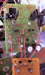
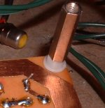
Here's my current front end solution, as you can see a wire to +ve, another wire to -ve and one each to the degeneration resistors for the long tailed pairs...
I ended up deleting 4 resistors from the main board, plus the 2 zeners, then added 3 resistors, 2 zeners, 2 caps and 2 transistors, on their own little board...
If I were going to respin the board I'd probably opt for the next level of complexity in what are a linked pair of ~3ma CCS...these are emitter follower CCS, adding one more transistor to each would improve it's technical performance, basically by DC feedback...
From a measured perspective the benefits are obvious, the amp's vital stats become totally stable across a very wide range of rails...PSU hum dropped by 10db, and the random noise floor seemed to drop by 3-5db, but this could easily have been an unintended layout change, it's a rat's nest right now...
I'm back to doing assembly of more output stage, then I have to build an even more powerful supply. As far as I can see I am at the limit of what I can do with 120v, so 240v here we come...there are benefits to working in the same garage as the (electric) dryer...the ultimate goal is 3hp into 2ohms...KSA-3HP ?
I sure hope you guys are having as much fun with this as I am...
Stuart
...didn't mean to give you a headache...
Bearing in mind this is totally unnecessary for any 'normal' KSA50 through KSA100 type amp...
Here's my current front end solution, as you can see a wire to +ve, another wire to -ve and one each to the degeneration resistors for the long tailed pairs...
I ended up deleting 4 resistors from the main board, plus the 2 zeners, then added 3 resistors, 2 zeners, 2 caps and 2 transistors, on their own little board...
If I were going to respin the board I'd probably opt for the next level of complexity in what are a linked pair of ~3ma CCS...these are emitter follower CCS, adding one more transistor to each would improve it's technical performance, basically by DC feedback...
From a measured perspective the benefits are obvious, the amp's vital stats become totally stable across a very wide range of rails...PSU hum dropped by 10db, and the random noise floor seemed to drop by 3-5db, but this could easily have been an unintended layout change, it's a rat's nest right now...
I'm back to doing assembly of more output stage, then I have to build an even more powerful supply. As far as I can see I am at the limit of what I can do with 120v, so 240v here we come...there are benefits to working in the same garage as the (electric) dryer...the ultimate goal is 3hp into 2ohms...KSA-3HP ?
I sure hope you guys are having as much fun with this as I am...
Stuart
Attachments
Al, I wasn't thinking of you re-doing the whole board, just a piggyback board that would hold Stuarts components and would wire directly down into exosting holes on the main pcb. This would make it an easy option to stay stock or go larger.
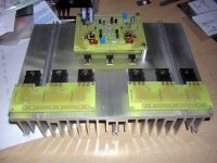
Here is a photo of the new boards all mounted up on the sink so far. I should have this up and running later tonight. Broke off one tap but that will dissolve when it goes in for anodizing.
One thing we may want to think about changing is the clearance between the screw mounting holes and the traces on the main board. Things get just a little too tight up by the pre-drivers. I'm not a fan at all of using nylon spacers and screws to mount boards but in this case I will have to in order to play it safe, I also generally use 6/32 hardware for doing this. The final position of the min board will be 1.250 inches above the driver board. This should give plenty of clearance Clarence.
Mark
Attachments
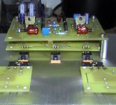
Closer shot showing driver board located underneath main board. This will allow me to drop the 4 wires directly down from the main to the driver board and then from the driver to the output boards. This is looking good for keeping wire length to a minimum. Some may choose not to break off their driver boards but to just jumper it over from the main board, making things even easier, but I didn't have the space on the sink to do this. All in all this will also make future repairs or mods alot easier to accomplish.
Attachments
Mark A. Gulbrandsen said:Closer shot showing driver board located underneath main board. This will allow me to drop the 4 wires directly down from the main to the driver board and then from the driver to the output boards. This is looking good for keeping wire length to a minimum. Some may choose not to break off their driver boards but to just jumper it over from the main board, making things even easier, but I didn't have the space on the sink to do this. All in all this will also make future repairs or mods alot easier to accomplish.
Are the Drains on the driver FETs all common?
Regards
Anthony
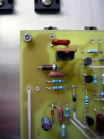
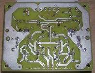
Showing the very slim clearance at the pre-driver corners between the foil and the mounting holes. What da ya think on this Al? Seems just a tad close for me with this kinda current available from the supply. I didn't feel safee placing my metal standoffs over the screws si the screws are just clamping the standoffs down for the moment till I get some nylon ones......
Mark
Mark
Attachments
Are the Drains on the driver FETs all common?
No FET's in this amp,. just bi-polor devices. There isn't really anyting common on these drivers anyway. I don't have the insulators installed on any of the devices yet...... have to go down to the dungeon and find em.
MArk
Coulomb said:Are the Drains on the driver FETs all common?
Drains? FETs? What do you think this is, a $%^$£%^ Aleph or something? 🙂
Mark A. Gulbrandsen said:Showing the very slim clearance at the pre-driver corners between the foil and the mounting holes.
Can you post a pic of the other side? I'm thinking of both the solder resist and plastic standoffs.
Exist also another mosfet amps with extraordinary parametres and sound quality, Al. Remember at Halcro 😀 .
I think there is more than just the Transistors on this thread that are Bi-Polar.
Please keep comments on this thread relevant to the thread or combine them with other useful information if one can. All the junk comments interspersed is the main reason this thread is almost 240 pages long.
Al, Here is a photo of the back side of the board. I have drilled the 4/40 holes for 6/32 clearance which is the next size up. There is not really even enough clearance for the 4/40 hardware with metal standoffs. I hate nylon, especially in hot running amplifiers. I doubt that nylon would even make a commercial rating were it used for this purpose in any amp.
Mark
Attachments
I would appreciate more clearance in every corner of the board.
The top holes have too little in my taste as well.
NO nylon spacers or studs please !
(the pics of the boards on the heatsink look like it is possible to have very little cable salad, goody goody)
The top holes have too little in my taste as well.
NO nylon spacers or studs please !
(the pics of the boards on the heatsink look like it is possible to have very little cable salad, goody goody)
Well, These boards are great but there is one problem that has got to be fixed even if it does mean more $$ charges from Advanced and that is that the hole size for both the driver and rail supplies to feed the boards is juat way too small. I can't even use my favorite 16 GA Teflon convered silver wire on these boards unless I tack them on the back... not a good thing indeed. Also normally I use 12 ga Teflon wire for the rails on the output devices and the output of the amp itself. These holes are way too small . But would be fine if one were using larger gauge ribbon cable.... and thats not what most here use.
The holes on Jan's boards were just right and we ought to move those over to this board as well.
Al, we've got to get on this problem. Those wanting to build large higher power versions will be out to lunch permanently on this till its changed.
I will still proceed with testing and such but will have to pick up smaller wire tommrrow in order to finish.
Mark
. But would be fine if one were using larger gauge ribbon cable.... and thats not what most here use.The holes on Jan's boards were just right and we ought to move those over to this board as well.
Al, we've got to get on this problem. Those wanting to build large higher power versions will be out to lunch permanently on this till its changed.
I will still proceed with testing and such but will have to pick up smaller wire tommrrow in order to finish.
Mark
Suggestion for New Thread
You know what, I've got a board set from the original (GB#1... yes this thread) and have a few questions. Not that I'll ask them now, this post is to cause trouble with this thread, which has become impossible to read.
Seems to me that with the multi THOUSANDS of posts that we have here It makes sense to make the GB#2 board a separate thread, so I don't have to wade though the hundreds of posts on that topic to find issues with my board from GB#1. Yes the pictures of that proto board and the fascinating comments are intriguing, but it doesn't help me with the original topic of this thread - the 1st board.
This thread should have moved from GB issues to construction issues, and instead it moved to a second GB. Now its impossible to find the few posts dealing with construction issues on the orig board.
Just my 2 cents, this second board(s) and the hundreds of posts dealing with it made the thread useless for its original purpose.
Have been trying to follow this thread since it started.. but something seems to have slipped...
When was "the other" PCB layout prEsented? and where ??
All along I thought we were still talking about Jan's layout.....
When was "the other" PCB layout prEsented? and where ??
All along I thought we were still talking about Jan's layout.....
Lgreen, this thread is tiny compared to the first Aleph X thread! Also, have you looked at the Wiki to see if your questions are answered there?
If you want a new thread to do with construction issues with Jan's board then start it. I'm sure we all here would conribute!
Mark, what are those wire sizes in metric, (or even mil)? It should be just a case of changing the drill file to sort the problem.
If you want a new thread to do with construction issues with Jan's board then start it. I'm sure we all here would conribute!
Mark, what are those wire sizes in metric, (or even mil)? It should be just a case of changing the drill file to sort the problem.
- Home
- Amplifiers
- Solid State
- Krell KSA 50 PCB