After looking over the KSA-100 schematics its really too bad that we didn't make room for a 4th output device on each output board!! I still look foreword to getting the boards though... would anyone out there be able to generate a set of gerbers for that larger board?????
Mark
Mark
I plan to use TO-3's as do some other folks. So for us it's P2P wiring and can use as many OP devices as the wife allows. 😉
I will try and use a bridged topology, and have 8 devices per bridge (i.e. same as KSA-100).
I will try and use a bridged topology, and have 8 devices per bridge (i.e. same as KSA-100).
Why does MJ1302& MJ3281 have large drop in Ft at low Ic and their
MJL1302 & MJL3281 is more normal?
Which amp sounds better, KSA100 or KSA50? Would like to build 1 but not both!
Tom
MJL1302 & MJL3281 is more normal?
Which amp sounds better, KSA100 or KSA50? Would like to build 1 but not both!
Tom
similar
The 2 amps are almost identical from a circuit perspective, so at this point I'm assuming where there are differences they will be absolutely minimal. There have been reports of the 50 sounding better, but if you have very inefficient speakers, the 100 may sound cleaner at high volumes because it has 3db more output and is therefore less likely to clip...
Based on the earlier entries in the thread, it looks possible, perhaps even easy to make a 50, then later increase voltage, output devices and heatsinks to end up with a 100...
Stuart
are the Ft charts screwed up...
Hi,
Assuming we are looking at the same datasheets, in the 500ma-5a range, there is virtually no difference between the transistors. The charts are (quite stupidly) scaled differently. One is linear, the other is logarithmic. If you plot data from one on the other they overlay each other for all the points that I tried...my charts only go down into the 100ma region, do you mean below this?
Stuart
tmblack said:Why does MJ1302& MJ3281 have large drop in Ft at low Ic and their
MJL1302 & MJL3281 is more normal?
Which amp sounds better, KSA100 or KSA50? Would like to build 1 but not both!
Tom
This goes back to the engineers vs. Listeners perceptions.
IMHO the design maybe the same, but I have experienced, less glare with lower rails and less grain with bridged designs.
The lower railed KSA-50 is on the list of many reviewers as one of the top ten amps ever made.... The KSA-100 is not.
On the Motorola data sheet the MJ1302A have Ft at 3Mhz @.1A Ic and the MJL1302A is about 16Mhz @.1A Ic both are figure 1.
Do you agree?
Tom
Do you agree?
Tom
the chart is incomplete...
Hi,
The chart I have for the mj* parts is so poorly scaled compared to the mjl* chart I'm not sure it is valid to compare, the error from reading the values is massive. For instance on my MJ* chart, the curve barely even extends to 0.1A. As it crosses 0.5A the thickness of the line is so great it spans the range from 10-20MHz. The earliest point that has any reliability is at 1A, where they are close to identical and they remain that way to their limits.
I think the differences you are seeing are real, but not as great as the **** charts can be read to imply. AFAIK the same die is used in both, so differences if they exist are going to be minimal.
By the way the Ft charts are derived from data collected at 1MHz, my guess is they'd be even closer at audio frequencies, where package capacitance and the like will have minimal effect.
Stuart
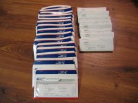
Shipped!
Hi All-
Email me if your not listed.
stgrab@yahoo.com
Did I mention I took the pile of money and bought a resort and am retiring? See pic attached (JOKING of course).
Domestic Mail Recipients
Mark G
VB 487 988 609 US
Stuart E
VB 487 988 759 US
George T
VB 487 988 541 US
Dennis C
VB 487 988 555 US
Kwok W
VB 487 988 590 US
Harry C
VB 487 988 569 US
John G
VB 487 988 586 US
William C
VB 487 988 572 US
Brian W
VB 487 988 515 US
Nicolas N
VB 487 988 524 US
Arif H
VB 487 988 507 US
Mike M
VB 487 988 498 US
David B
VB 487 988 538 US
International Mail Recipients
Jonathan C
VF 243 790 156 US Insurance
LZ 690699341 US Package
Anthony T
VF 243 790 139 US
LZ 690699284 US
Frank R
VB 487 983 120
LZ 644118279 US
P.D.
VB 487 983 133 US
LZ 644118319 US
Richard P
VF 243 790 195 US
LZ 690699338 US
Jan D
VF 243 790 173 US
LZ690699409 US
Arne K
VF 243 790 142 US
LZ 644118305 US
I Chien W
VB 487 983 080 US
LZ 644118296 US
JH H
VF 243 790 125 US
LZ 69069929US
Anthony K
VB 487 983 102 US
LZ 690699372 US
Dominique B
VF 243 790 160 US
LZ 690699390 US
Arthur B
VB 487 983 116 US
LZ 644118265 US
Ed H
VF 243 790 187 US
LZ 690699369 US
Walter G
VB 487 983 093 US
LZ 644118282 US
Aaron B
VF 243 790 108 US
LZ 690699307 US
Wim S
VB 487 983 076 US
LZ 690699386 US
Attachments

For MJ1302A datasheet:
http://www.alldatasheet.com/datasheet-pdf/view/MOTOROLA/MJ1302A.html
Ft is clearly seen to fall with Ic in figure 1.
Could affect stabilty out to 1 Mhz.
Tom
http://www.alldatasheet.com/datasheet-pdf/view/MOTOROLA/MJ1302A.html
Ft is clearly seen to fall with Ic in figure 1.
Could affect stabilty out to 1 Mhz.
Tom
Did I mention I took the pile of money and bought a resort and am retiring? See pic attached (JOKING of course).
Hello Rabstg, this resort you attached a picture of is in Dubai. If you are not a guest, it costs $75 US just to get past the front gate on the mainland. It has it's own heliport and it's suites cost many, many, many thousands a night. If you had made off with the loot, you would not even have enough to pay to use the bathroom! 🙂 🙂 🙂
Regards and thanks
Anthony
hmm,
Tom,
The datasheets there are a little different from mine, and you are quite right, the 1995 datasheet from motorola for the mj* transistors shows the gain plummet below a certain threshold...makes the transistors look quite different from the more recent datasheets for the on-semi mjl* parts...
As an interesting exercise you should compare the motorola datasheets from the same year for the both transistors...the 1995 datasheets for the mj & mjl parts show exactly the same characteristic and as far as I can tell are absolutely identical except for differences caused by the packaging...
As far as I can tell on-semi has updated some but not all of the datasheets. The mjl docs are clearly different, the mj ones not much at all...
On semi has either learned to make the transistors better, or they have learned to measure them better...but in either case I still believe the transistors will be virtually the same, or at least as close as any pair of transistors made from the same die.
Stuart
On Their Way
Excellent!!!
I can't wait, might start buying up on small components now 🙂 *yay*......
How long does int priority mail take?
Aaron
Excellent!!!
I can't wait, might start buying up on small components now 🙂 *yay*......
How long does int priority mail take?
Aaron
How about polypropylene capacitors? Any good cheap sources?
Solens seem least expensive here aside from no names.
Tom
Solens seem least expensive here aside from no names.
Tom
Hi All-
SO I rxed the brds and sent them out..
As I was looking at them I was scratching my head over C102, 103 and 104.
I have to ask why the back to back caps(102 & 3) when you have the bypass(104)?
And please excuse me if I missed it in the earlier portion of the thread.. If it was mentioned please let me know the post # and I will read quietly in the corner...
Boards are on the way. For those of you still collecting parts:
http://mcm.newark.com/
2SC2240
TOSHIBA TRANSISTOR TO-92 120V .1A .3W ECB $0.27
2SC3955
SANYO TRANSISTOR TO-126ML 200V .1A 7W ECB $1.09
2SA970
TOSHIBA TRANSISTOR TO-92 -120V -.1A .3W ECB $0.28
All other transistors at:
http://www.onsemi.com/
Prosit
http://mcm.newark.com/
2SC2240
TOSHIBA TRANSISTOR TO-92 120V .1A .3W ECB $0.27
2SC3955
SANYO TRANSISTOR TO-126ML 200V .1A 7W ECB $1.09
2SA970
TOSHIBA TRANSISTOR TO-92 -120V -.1A .3W ECB $0.28
All other transistors at:
http://www.onsemi.com/
Prosit
For all us aussies 2sc2240 and 2sa9** found at Wagner electronics
http://www.wagner.net.au/
That's easy because they were $0.81 for one type and $0.7* something for the other 🙂 That's cheap enough for me!! I've decided to go for the MPSA56/06 i think it was combo too for the input, see how it goes, i've got MPSA42/92 here anyway in case 🙂
Anyone know anyone who sells good caps and resistors (for the board) in australia? I can buy o/s, if i have to , trying to avoid it as much as possible... 🙂
Aaron
While waiting for the boards, i am collecting parts and looking to the pinnings and distances on the PCB Jan Made.
It seems to me that the pinning on the PCB board from R126 and R144 (the trim pots for bias) are not correct.
i will try to explane, but my english is not too good, sorry for that:
On Jan's schematic one endpin from a pot is connected to the wiper of that pot, the other endpin goes to Q108.
On the PCB layout the two endpins from each pot are connected and the wiper goes to Q108.
I looked at the datasheet from the cermet bourns pot, and the middle pin is the wiper.
I hope i am wrong?
- Home
- Amplifiers
- Solid State
- Krell KSA 50 PCB