wim:
Sadly I have to admit that you're right in your observation I had two 10-turns pot in my lib. and have obvious chosen the one with "wrong" pin-configuration 😡
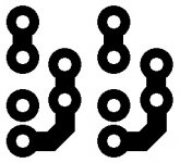
On Jan's schematic one endpin from a pot is connected to the wiper of that pot, the other endpin goes to Q108.
On the PCB layout the two endpins from each pot are connected and the wiper goes to Q108.
I looked at the datasheet from the cermet bourns pot, and the middle pin is the wiper.
Sadly I have to admit that you're right in your observation
I had two 10-turns pot in my lib. and have obvious chosen the one with "wrong" pin-configuration 😡ACD said:wim:
Sadly I have to admit that you're right in your observation
A short note on the fix please.
Regards
Anthony

Great!
Thanks for the fix! I was looking at it thinking it didn't look right, but let it slide as i'm not to the stage of setting it up yet! haha
Thanks for the fix info
Aaron
Thanks for the fix! I was looking at it thinking it didn't look right, but let it slide as i'm not to the stage of setting it up yet! haha
Thanks for the fix info
Aaron
is it possible to use 2sc3421 instead of 2SC3955? Every thing looks good I have a few of these so I may as well try it. I dont have the schematic handy, whats the voltage across the 2SC3955? 2SC3421 is good for 120V at 1 amp and 10Watts.
K-amps said:The boards came in today... for lack of a better word,
they are PERFECT!!
Thanks to Troy and Jan for making this possible.
Cheers!!
I wanted to wait until someone rx'ed their boards before I said anything.
Did you notice the boards are 50% thicker than "regular" PCB's(.093" instead of .062")? Also the copper traces are 1.5 oz instead of the usual 1 oz.
I did that for 2 reasons.
1. More solid main board that will be less likely to bend or pick up micro phonics.
2. Output boards should be able to withstand the heat and current better than a thin board ensuring many years of trouble free operation.
Hey Jan-
Thank you for the super fast updat on the fix!
To Luke : Instead 2 SC 3955 you can use every NPN transistors in ML ( full insulated ) TO 126 case. Working voltage Uce of this transistor at this position is very low, so you have practicaly any limits of breakdown voltage. Jan designed this type of transistor for easy mounting ( any problems with insulation ), but concrete type isn't critical at this position 😎 .
Thanks for the packaging...
The boards are great, the quality of the packing was stressed for mine, someone decided to try and test the bounce and tear characteristics of the package...
Under normal conditions there is a max of perhaps 15v across the 2sc3955, when you are trying to drive 50amps into a 1ohm load, most of the time it will be much less than that, I think it is only as the amp moves into class B that any big voltage swing can occur.
What's the preferred method for cleanly snapping the scores?
Once again thanks for a great job guys.
Stuart
Re: Thanks for the packaging...
Personally, I use much the same method as with wall tiles. Place a thin sliver of wood under the score, and push down firmly on both sides of the board.
Stuart Easson said:What's the preferred method for cleanly snapping the scores?
Personally, I use much the same method as with wall tiles. Place a thin sliver of wood under the score, and push down firmly on both sides of the board.
rabstg said:
Did you notice the boards are 50% thicker than "regular" PCB's(.093" instead of .062")? Also the copper traces are 1.5 oz instead of the usual 1 oz.
Yes I did notice they were the thickest boards I have seen, lol.
My 10 boards arrived today..... All fine and VERY well packed! Thanks again for everyones effort!!! Will start collecting parts tommrrow.....
Mark
Mark
Boards were waiting when I got home
Troy and Jan,
Thanks, they will make a very nice amp. Hope to post pictures once built.
George
Troy and Jan,
Thanks, they will make a very nice amp. Hope to post pictures once built.
George
Hi All-
After snapping the boards apart, a sharp razor will flatten and clean off the edges.
Another messier way is fine grit sand paper.
After snapping the boards apart, a sharp razor will flatten and clean off the edges.
Another messier way is fine grit sand paper.
ACD said:Hi all 😉
Thanks for your cooperation and understanding 😉
Hey Jan-
You drew the schematics and designed the PCB's.
Then you POSTED for ALL to critique.
If anything is wrong, it is ALL of our fault for not catching it. And anyone can suggest fixes to problems found. It is NOT just your responsibility!
This was/is a GROUP design and purchase. We all have responsibilities.
But thanks anyway for the quick suggestion on the fix!
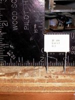
emitter resistors...
Hi All,
I was thinking I can perhaps assist anyone still collecting parts...
I have hundreds of panasonic 10w, 0.68 resistors, they are about the size of a stamp, and maybe 3mm thick, about 1/4oz each. If you want a sane number, like 4/8/12 whatever, send me an email, I'll give you my address, then you send me a postage paid envelope, to wherever you want them delivered. You can do the math to get the weight, packaging, postage right etc, other than that they are free for the asking, assuming you bought boards for the ksa50...or contributed to the thread, before this posting of course...
Stuart
Attachments
I second that motion.
All other aspects of the board are primo. The fix is a minor deal.
None of us ever makes any misteaks?
Prosit
All other aspects of the board are primo. The fix is a minor deal.
None of us ever makes any misteaks?
Prosit
- Home
- Amplifiers
- Solid State
- Krell KSA 50 PCB