Looks good jan. Do the ??? signs for ZD101/ZD102 mean that the discribed value is not sure? Maybey any other know more about this, and for the value of R124.
By the way, in the earlyer schematics of Jan, there are diodes D2012 ansd D202. I can't find them on the PCB and on the bill of materials.
Krelloutputs
Hi acenovelty.
Original output transistors were TO-3 MJ15003/MJ15004.
http://home.ca.inter.net/~lloyd.maclean/Krell/Krell.htm
Direct link to the KSA-50 schematic:
http://home.ca.inter.net/~lloyd.maclean/Krell/KSA50.pdf
acenovelty said:Just curious. Did the KSA 50 use plastic output transistors like the MJL21194/93 and MJE15033/32?
Seems like both NUTTTR and Stuart Easson confirmed "The schematics I have show mj15003/4 pairs" albeit with a small disclaimer about
"the choice of output transistors is a somewhat sensitive subject, close to religion or politics... "
But then if this is a clone, it might be a good idea to publish a parts list that reflects the original components accurately.
The MJ15003/4 sell for about 2 bucks and 25 can be had from onsemi as free samples.
Prosit
Hi acenovelty.
Original output transistors were TO-3 MJ15003/MJ15004.
http://home.ca.inter.net/~lloyd.maclean/Krell/Krell.htm
Direct link to the KSA-50 schematic:
http://home.ca.inter.net/~lloyd.maclean/Krell/KSA50.pdf
output devices (again)
Hate to bring this up again, but I wasn't crazy (this time)! The MJL21193 and MJL21194 are TO-220 type package and the MJ21193 and MJ21194 are TO-3 type package. Other than this the data sheets look like photocopies of each other. I must have missed an "L" when I retyped in the parts.
As I said before, my heatsinks are predrilled for TO-3, so would I be better off using MJ21193/94? Any reason not to (other than that I wouldn't be able to use the output boards)?
By the way, which is considered to be a better package for heat dissipation?
A few comments
acenovelty:
The plastic MJL's where chosen due to the fact that the risc for shortenings are lower than for TO-3's, and because they are easier to fit for most of the diy'ers...
The MJL's are also avaiable as samples from Onsemi 😉
wim:
Yes! Thats because I'm not sure of the correct value 😉
And D201 and D202 are not on the PCB's any more. These >120V/1A diodes must be fitted separately......
lgreen:
You can use any type you like or prefer 😉
The Output Board PCB's are just made for 340G-02 housing (the MJL'S) to give most diy'ers an easy way to build this clone😉
You can use any type you like or prefer 😉
The Output Board PCB's are just made for 340G-02 housing (the MJL'S) to give most diy'ers an easy way to build this clone😉
Re: output devices (again)
According to the data sheets both have a resistance of 0.7 degC/W. Presumably this is them bolted to the sink- it may be that the plastic transistors will show a lower resistance if they're clamped to the sink with a big chunk of aluminium, so heat is conducted out of both sides of the package.
The plastic versions are rated at 200W, the metal 250 by the way.
I'm thinking about isolating the heatsinks from each other and ground and bolting the trannies straight onto them without an insulating pad, in the interests of reducing thermal resistance.
lgreen said:
By the way, which is considered to be a better package for heat dissipation?
According to the data sheets both have a resistance of 0.7 degC/W. Presumably this is them bolted to the sink- it may be that the plastic transistors will show a lower resistance if they're clamped to the sink with a big chunk of aluminium, so heat is conducted out of both sides of the package.
The plastic versions are rated at 200W, the metal 250 by the way.
I'm thinking about isolating the heatsinks from each other and ground and bolting the trannies straight onto them without an insulating pad, in the interests of reducing thermal resistance.
RABSTQ, i just edited the total field of the WIKI. The total was not 74 or so wat, but 92. (Please dont order a wrong number of PCB's)
Well I'm going to use MJL4281A/MJL4302A and drivers MJE15043/35,only because I've got them in my spares box.
I thought this might turn up here on what to use.
I thought this might turn up here on what to use.
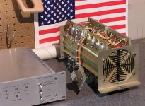
For all you builders who have never seen a KSA 50:
http://community.webshots.com/album/249287604tVVTpP
Prosit
http://community.webshots.com/album/249287604tVVTpP
Prosit
getting started with heatsinks
My Mystery Amplifier should get me 1/2 way there, well at least as far as heat sinking goes.
Its big enough I suppose for an 8 channel KSA-50, but I'll probably use extra output devices on each channel and use half of it, saving the other half for something else.
My Mystery Amplifier should get me 1/2 way there, well at least as far as heat sinking goes.
Its big enough I suppose for an 8 channel KSA-50, but I'll probably use extra output devices on each channel and use half of it, saving the other half for something else.
Attachments
I'm going to be using MJE15030/31's as drivers from memory... I'm swimming in parts here, they are here somewhere....
I'm going for 4 pairs of outputs per channel, possibly depending on where it sits in the SOA, i might make it 6, i *think* the driver pairs and circuits will "support" it as such, i may need another pair of drivers - the KSA-100 had 2 pairs of drivers however only had 4 outputs, which makes me wonder a little....
Aaron
Jan - the parts you mentioned - 120v - 1a diodes - what were they for? i can't see where they'd popped up on original schematics
So Jan, what do you consider to be the best output devices for this design if you were to stick with a TO-220/247 style casing?
Regards
Anthony
Regards
Anthony
NUTTTR:
The diodes are optional, however used in most amplifiers.
Their purpose is to prevent reverse collector-emitter voltages due to capasive and inductive loads (like the speakers crossovers and voice coil etc. )
Coulomb:
Why TO-247 casings? The selection is limited, however the MJW21193/94 from Onsemi are quite nice 😉
Bank tfrs
Hi all who sent bank Transfers-
I have rx'ed 2 transfers thus far.
Ipanema and Jozua
All others please reverify information and contact me via email.
Hi all who sent bank Transfers-
I have rx'ed 2 transfers thus far.
Ipanema and Jozua
All others please reverify information and contact me via email.
Payment deadline
Hi All-
Payment deadline for boards will be tomorrow at noon.
I will be ordering the PCB's at 4 PM my time. (Central Standard Time USA)
Please email with any questions and sorry for any delay or poor communication.
Hi All-
Payment deadline for boards will be tomorrow at noon.
I will be ordering the PCB's at 4 PM my time. (Central Standard Time USA)
Please email with any questions and sorry for any delay or poor communication.
- Home
- Amplifiers
- Solid State
- Krell KSA 50 PCB