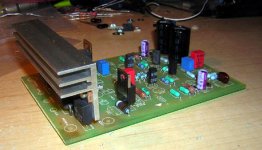
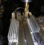
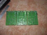
I found some surplus heat sinks today that allowed me to just about duplicate the original Krell heat sink. I machined back some of the fins and then repositioned Q-110 so I could keep the heat sink straight with the PCB edge. One driver is on each sode of the sink and C-108 will be on the bottom of the board. Its worked out well so far although this is the reverse of the original Krell arrangement. The bias transistir is in the center of the heat sink and will be jumpered over to its connections and insulated with heat shrink. So hopefully things will track well...... The NTE transistors are just temporary till the real stuff arrives.
Mark
Mark
Attachments
Mark A. Gulbrandsen said:I found some surplus heat sinks today that allowed me to just about duplicate the original Krell heat sink. I machined back some of the fins and then repositioned Q-110 so I could keep the heat sink straight with the PCB edge. One driver is on each sode of the sink and C-108 will be on the bottom of the board. Its worked out well so far although this is the reverse of the original Krell arrangement. The bias transistir is in the center of the heat sink and will be jumpered over to its connections and insulated with heat shrink. So hopefully things will track well...... The NTE transistors are just temporary till the real stuff arrives.
Mark
Got extras? 😀
Very nice Aaron, i hope it works fine.
By the way, did you use the capacitor values as named on Jan's partlist, or did you use other values (because of the discussion on this forum about the values from some of the capacitors)
Succes with the tests!!
By the way, did you use the capacitor values as named on Jan's partlist, or did you use other values (because of the discussion on this forum about the values from some of the capacitors)
Succes with the tests!!
It works
I finished one amp board this morning.Powered it up with my bench psuat 30 0 30.I preset the Dc offset pot in the middle 2.5 k and it wasnt far off.I set the bias current at 2.5 Amps to start and managed to get the main heatsink to 65 degrees.I put the bias transistor on the main heatsink as ive done before with other amps ive made.q109 and q110 are getting pretty hot so think i'll have to find some larger heatsinks for them but on the whole the amp works well.
I tryed to send some pics but it wont let me upload them says they are too big !! ?
Hope to resolve this
Regards
Anthony
Anyone figured out whats the Max VDC rails that can be applied to these input boards. (Regardless of Biass level on output.) ?
Will these handle 70-0-70 vdc rails? i.e. the diff and VA stages?
Will these handle 70-0-70 vdc rails? i.e. the diff and VA stages?
Anthony-
I'm not building one of these (yet) but am very interested. If you want to email me your pics, I'll stick them on my web site and post a link to them. I'm sure people would like to see them.
I'm not building one of these (yet) but am very interested. If you want to email me your pics, I'll stick them on my web site and post a link to them. I'm sure people would like to see them.
Anthony, You say 2,5 A bias current. You mean 0,83 A per output device? (if you use 3 outputdevices per rail conform jan's schema).
I'm glad to see that the Krell-Clone is working 😉
Please post your changes to the parts list, and I will update it on the delta web page 😉
Please post your changes to the parts list, and I will update it on the delta web page 😉
Good idee Jan. Specialy in case of the values from some capacitors, becouse there was some discussion about.
For Capacitors 105 and 106 i used a 33 PF polystyrene cap.I think thats all i changed from Jan's part list, I used 1 Ohm base resistors on the output boards.
Regards
Anthony
Regards
Anthony
Hi All-
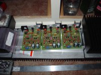
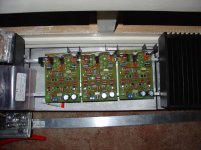
I noticed on Aaron's photos he is using terminals for his inputs. I will likely go the same route if I can find them so I can just parallel the signal ground and the board ground to the same point.
Aaron-
Where did you get the batch of heat sinks? I see several lined up on the floor. Also, will you be using one heat sink per channel? That is about the capacity they looked to be able to handle.
- Home
- Amplifiers
- Solid State
- Krell KSA 50 PCB