On this site, when most of us talk about cloning an amplifier we mean the circuit, not copying the original. You certainly did not follow the link or you would not have made this comment.
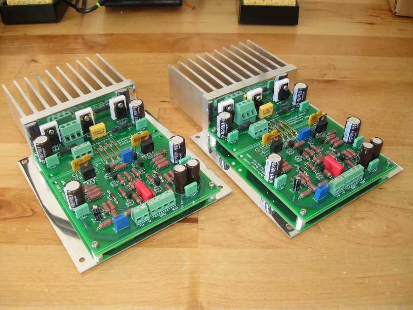
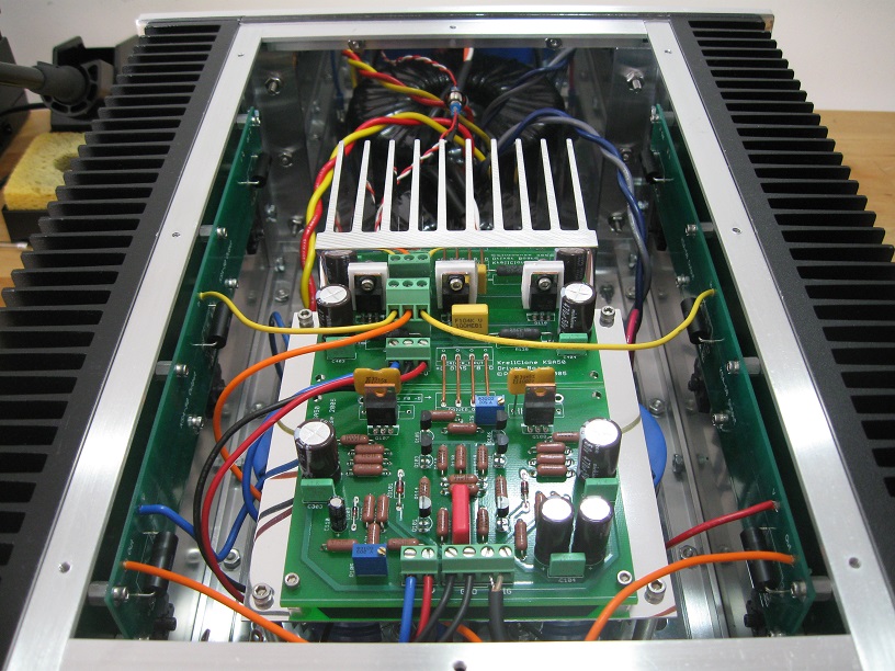
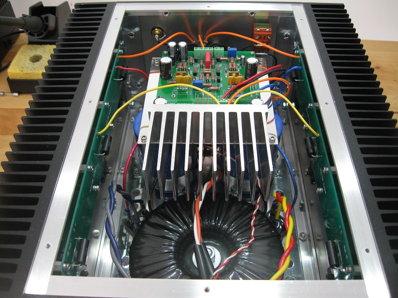
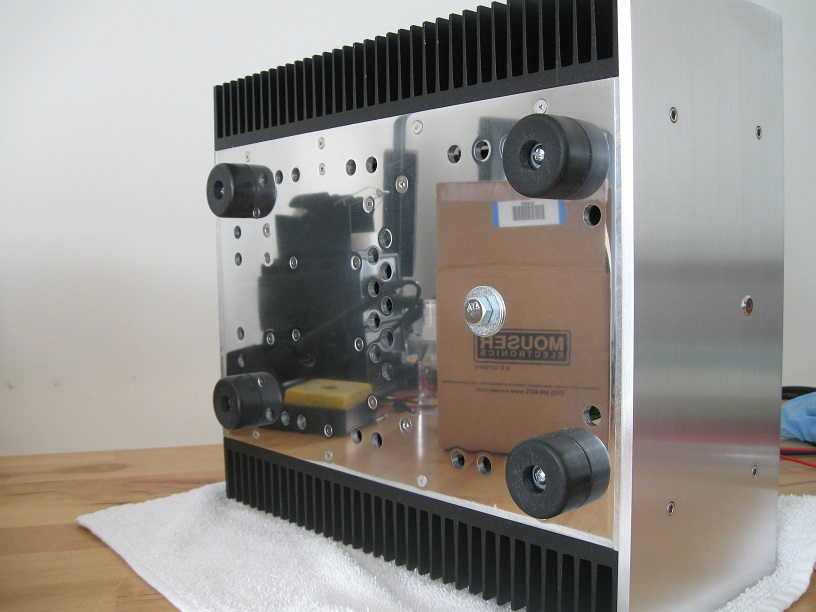
Having followed the link can I just say your build is magnificent, from concept to execution. I only wish I had a fraction of your skill. My KSA50 will be a straight clone and I will enjoy it no less than anyone else's build.The main PCBs are mounted on an aluminum plate, supported by four standoffs attached to the bottom plate. I replaced the drivers' heat sink with a larger one.
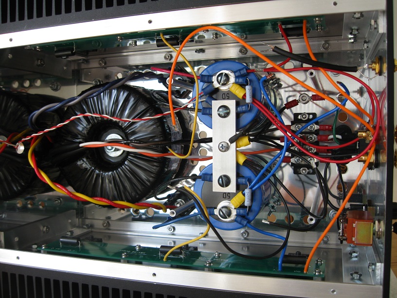
I reinstalled the transformer and connected it.
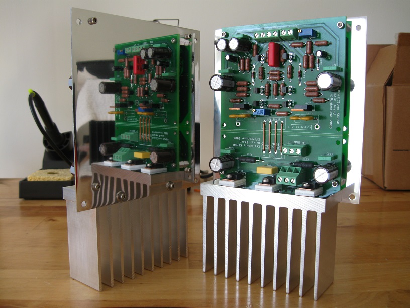
Next I put the PCB assembly back in its place.
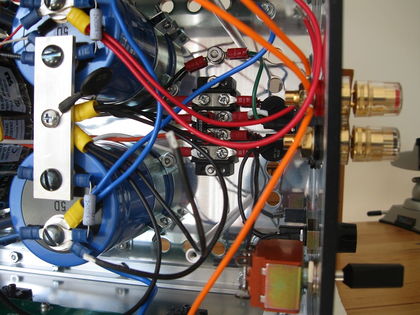
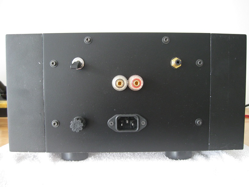
And here is a view from the back.
A closeup of the connections on the bottom and back plates.
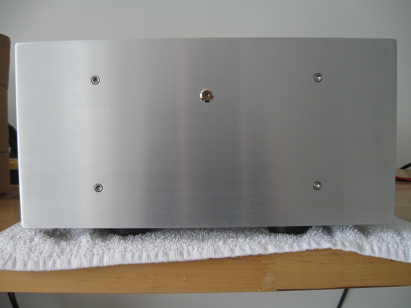
The newly created front panel
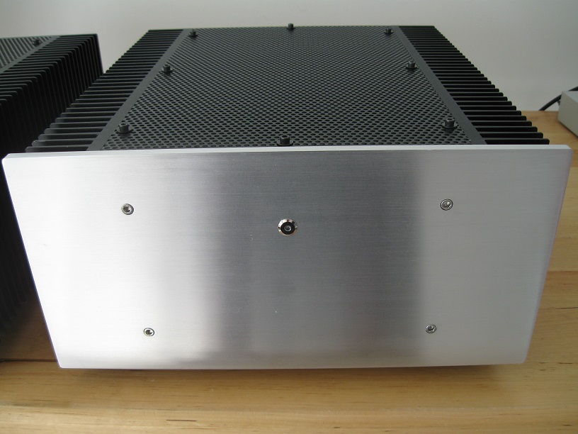
The back plate.
And the bottom plate
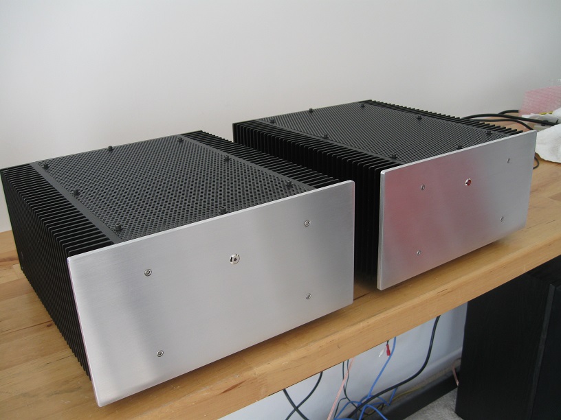
And finally, the mono-blocs complete, side-by-side.

Thank you for the compliment. Earlier in this thread many of the builders went the active cooling way because it is practical and that is either what they had available or could afford at the time. Large heatsinks were not easy to purchase in small quantities back then, but I wanted to build my clone my own way and imported the heatsinks from Australia.
You should make yours the way you want, without regard for anyone's comments on your choices. This is, after all, entertainment not brain surgery.
🙂
You should make yours the way you want, without regard for anyone's comments on your choices. This is, after all, entertainment not brain surgery.
🙂
Could you tell me what heatsinks on the PCB you used for your build please? The ones for the VAS and LTP.
Ta.
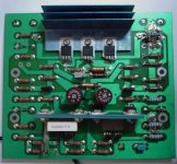
I have attached a picture of an original, albeit beat-up, Krell PCB. The LTP transistors don't need a heatsink. The VAS devices you can solder upright, as shown, attached to a 5 or 6mm thick piece of aluminum to serve as heat spreader.
Attachments
Grimberg - great looking build. Mine is more of a restomod, mainly restoration with some low-key modifications.
Thanks for the cct Berlosconi, can I trouble you for a larger / higher resolution file?
Mega_man are you using a CLCLC psu? I'd like to drop the voltage from the trafo on mine, at the moment it is 56v unloaded. I think a few inductors & caps in the psu will allow me to tune the B+, B-.
Thanks for the cct Berlosconi, can I trouble you for a larger / higher resolution file?
Mega_man are you using a CLCLC psu? I'd like to drop the voltage from the trafo on mine, at the moment it is 56v unloaded. I think a few inductors & caps in the psu will allow me to tune the B+, B-.
Grimberg, is it necessary to use such a big heatsink for the drivers transistors? I plan to use something similar to the original.
Grimberg, is it necessary to use such a big heatsink for the drivers transistors? I plan to use something similar to the original.
I decided to use natural convection in my clone. In that case, the large heatsinks are the right size to use 2 per channel. In your case, since you are taking the forced convection approach, you will need to monitor the heatsink temperature, making sure it does not exceed 60 degrees centigrade. If your heatsink and fan combination can achieve that, it should be all right.
firestorm,
You were looking for the schematics matching your PCBs. I believe you will find them at the link below:
https://www.diyaudio.com/forums/solid-state/308366-kma-100mkii-ksa-50mkii-rebuild-sanity-check-requested.html#post5092729
You were looking for the schematics matching your PCBs. I believe you will find them at the link below:
https://www.diyaudio.com/forums/solid-state/308366-kma-100mkii-ksa-50mkii-rebuild-sanity-check-requested.html#post5092729
firestorm,
You were looking for the schematics matching your PCBs. I believe you will find them at the link below:
https://www.diyaudio.com/forums/solid-state/308366-kma-100mkii-ksa-50mkii-rebuild-sanity-check-requested.html#post5092729
yes, I was - it's different from the Pinkmouse pcb I also have which is already populated. Looks like I'm going to be making a BOM and then ordering parts soon.
thanks Grimberg.
To be honest, the right way to provide efficient environment for KSA-50, in my humble opinion, is shown on the photo below - taken from the thread "My Completed Krell KSA 50 Clone - Pics".
Streamlined design, well sized heat sinks, proper overall topology. Nothing to add or remove. Almost perfect.😎

Streamlined design, well sized heat sinks, proper overall topology. Nothing to add or remove. Almost perfect.😎
I agree this is a really nice looking quality build.To be honest, the right way to provide efficient environment for KSA-50, in my humble opinion, is shown on the photo below - taken from the thread "My Completed Krell KSA 50 Clone - Pics".
Streamlined design, well sized heat sinks, proper overall topology. Nothing to add or remove. Almost perfect.😎
I have also done mine as two mono block amps because of space and they double up as speaker stands.
My amps are still not finished I will post some pictures when finnished.
I'd love to see your finished amplifier because I was present while that 'drama' with your 'faulty' board was unfolding, 'live' , in real time, so to speak and then abruptly, conversation has stopped, without a closure. Great to hear that you've managed to end-up with successful build.I agree this is a really nice looking quality build.
I have also done mine as two mono block amps because of space and they double up as speaker stands.
My amps are still not finished I will post some pictures when finnished.
I personally like simple but efficient equipment. However, technically sound, with properly cut, perpendicular edges and everything that reveals well premeditated work.
Cheers.^_^

I'd love to see your finished amplifier because I was present while that 'drama' with your 'faulty' board was unfolding, 'live' , in real time, so to speak and then abruptly, conversation has stopped, without a closure. Great to hear that you've managed to end-up with successful build.
I personally like simple but efficient equipment. However, technically sound, with properly cut, perpendicular edges and everything that reveals well premeditated work.
Cheers.^_^
Berlusson I thankyou and others that have helped me. unfortunately I have spent a lot of time ill in hospital due to having cancer im having chemo at moment.
Funds also dried up being unable to work so didnt want to post or show unfinished projects.
They are working fine usable and sound great.
Still haven't made my pre amp yet ive just used a passive volume control.
Dave,
Recently, I've watched a BBC series by Jim Al-Khalili about the Arab contribution to modern Science. Some medieval Arab scholar stated that God could not send an ilness upon us without sending also a medicine that heals it. I hope your doctors would find the right medicine for you and ensure your full recovery.
Never give-up.🙂
Last edited:
@ chilly,
Beautiful work!
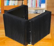
Does anyone know the origin of the part case below? Were they from a group buy during the days of Pink Mouse's clones? A fourth heatsink encloses the case to give a HS on every side.
[I have a set of eight of these heatsinks - which I intend using for other purposes. One had Krell clone boards soldered up and mounted.]
Thanks.🙂
Beautiful work!
Does anyone know the origin of the part case below? Were they from a group buy during the days of Pink Mouse's clones? A fourth heatsink encloses the case to give a HS on every side.
[I have a set of eight of these heatsinks - which I intend using for other purposes. One had Krell clone boards soldered up and mounted.]
Thanks.🙂
Attachments
Many thanks Pink Mouse...you are probably right. I bought a lot of AndrewT's (R.I.P) workshop contents and as there is a set of your boards for a Krell clone - there were some blue boards (Krell clone) fitted in one case - I assumed that that is what they were made for Krell clones.
Thanks again.
Thanks again.
I'm building a KSA50 clone based on Jim's Audio boards and his KSA50 clone heatsink.
One area that I'm confused with is the standoffs of the PCB from the heatsink. These standoffs attach to one the mounting bolts of the TO3 output devices and hence are live at the +48Vdc supply (-48Vdc on the PNP boards), if the standoff and mounting screws are metal. On the main PCB the holes for the standoffs are electrically connected to the +48Vdc and -48Vdc tracks (NPN and PNP respectively).
This does seem strange as there is already a +48Vdc/-48Vdc wire between the main PCB and the driver boards on the heatsink. So why electrically connect the boards through the standoffs???
My question is whether I should be insulating the standoffs with say a nylon spacer at the main PCB end, or that the live standoff is 'normal'?
- Home
- Amplifiers
- Solid State
- Krell KSA 50 PCB