My KSA-50 is still functioning as well... no issues at all. I should probably re-cap my power supply I suppose. I also still have all the versions of the prototype boards that I built and tested during the beginnings of this thread. I should really get those framed and hang them on the wall in my listening room... with a slogan under them saying:
"860 Pages, 8599 replys and 1,550,825 views"
Mark
"860 Pages, 8599 replys and 1,550,825 views"
Mark
I've been busy building new amps so was going through some of my older ones looking for ones I may want to retire so I could use the transformers, cases and heatsinks. I hooked up the KSA50's and gave them a good listen. Man they sound nice! They will live on for sure. They didn't take a back seat to any of the others. The Aleph-X is history and probably the Superamp next but the KSA's shall remain. Glad I built them.


Member
Joined 2009
Paid Member
Terry - that's a superb build.
I remember you saying the SKA sounded somewhat similar - did you try running the SKA in Class A ?
Did you ever get to compare the Krell with the JLH 1969 ?
Rgds.
I remember you saying the SKA sounded somewhat similar - did you try running the SKA in Class A ?
Did you ever get to compare the Krell with the JLH 1969 ?
Rgds.
Hi Bigun,
I didn't ever try the ska in class A. The ska seems right on the edge of oscillation so I kind of quit while I was ahead. I would like to try your version sometime.
I haven't A/B'd the Krell and JLH. The JLH is not on a proper heatsink right now but I can try that in the next couple of days. I remember being surprised at how good the JLH sounded for such a simple design.
Hello Everyone,
Here are a few AP curves of my KSA-50 clone. Below are a few specs of my amp(s)..
Dual Mono Design (Separate chassis)
Rail Voltage +/- 35VDC
Capacitance per rail - 40,000uF x 2
Emitter Resistors - 0.22 Ohm
Bias Voltage (across 0.22 Ohm emitter resistor) - 100mA (Based on heat sink used)
Compensation caps:
Input - 680pF
VAS - 39pF


In addition, I am running a pair of La Scala's (Ported) and I don't really need the Krell clone to be biased for 50 Watts into 8 Ohms.
Here are a few AP curves of my KSA-50 clone. Below are a few specs of my amp(s)..
Dual Mono Design (Separate chassis)
Rail Voltage +/- 35VDC
Capacitance per rail - 40,000uF x 2
Emitter Resistors - 0.22 Ohm
Bias Voltage (across 0.22 Ohm emitter resistor) - 100mA (Based on heat sink used)
Compensation caps:
Input - 680pF
VAS - 39pF
In addition, I am running a pair of La Scala's (Ported) and I don't really need the Krell clone to be biased for 50 Watts into 8 Ohms.
Hello Everyone,
Here are a few AP curves of my KSA-50 clone. Below are a few specs of my amp(s)..
May I know the bandwidth setting (22k, 30 k, 80 k) of AP for THD+N?
May I know the bandwidth setting (22k, 30 k, 80 k) of AP for THD+N?
For the THD+N test it was set to 80kHz, which is what I usually leave it set on for home amp testing.
I also use the >500kHz filter, but that is just to peek at the top end.
Hi everyone, could I have some constructive criticism (or just criticism ) of a version of the KSA clone I am working on.
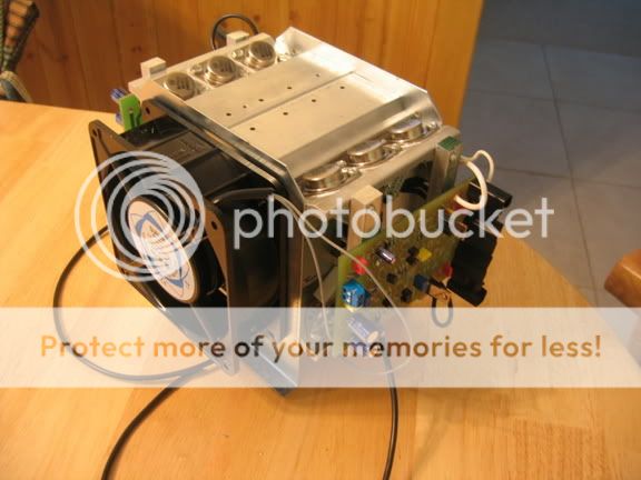
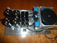
After several different builds of this amplifier using different rail voltages ( up to +-40V ) and using both fan cooling and huge passive heatsinks, both of which cause problems with either noise or a chassis that is very obtrusive in a domestic environment, I think I have come to a compromise.
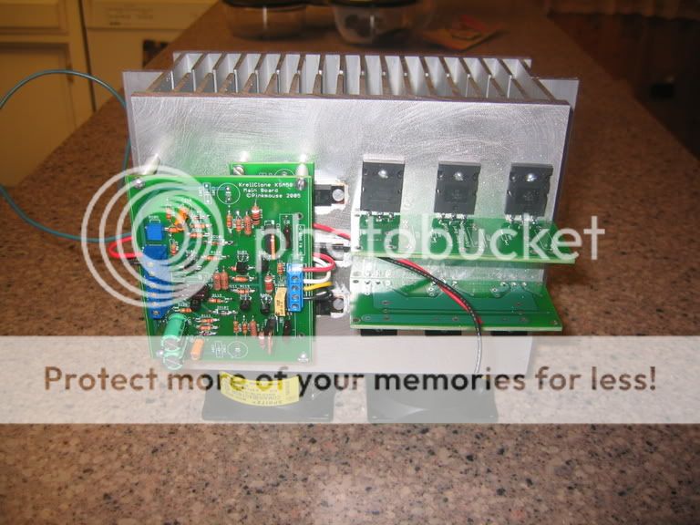
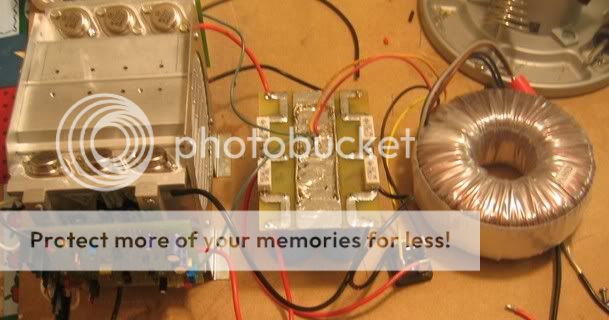
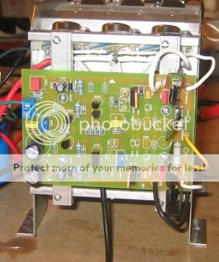
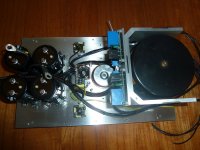
I am now using +-26volts rails, 300VA transformer per channel, 47.000uf per rail, passive heatsinking in a finished size of 310mm wide x 400mm deep x 140mm high. Hopefully this gives me 30W class A into 8 Ohms with a heat dissipation of 70W per channel. The output stage is overkill for the amount of power output, but I had the transistors (MJL21193/94 ) and the PCB's so I used 3pairs per channel with 0.68Ohm emitter resistors biased at 310mV . I have also taken from the secondaries of the transformers a separate feed to rectifiers and filter capacitors to supply the amplifier up to but not including the driver transistors
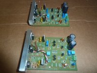
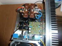
The heatsinks are thermally insulated from the rest of the chassis to keep internal components as cool as possible. the transformers are screened and all A/C wiring is in twisted pairs. I have temporarily connected one output stage to check results so far, as can be seen in one of the pictures I have attached. I can not hear any hum with my ear to loudspeaker cone, bias and offset remain rock steady and the sound to my ageing ears is just what I want. I have fitted loudspeaker protection boards.
I have not, put any bypass caps across filter caps, have not used any soft start for the transformers (300VA ) have not fitted fuses in rails, just on primaries.
Please give me your views as to anything else I should consider before finally assembling.
Thanks
Alan
After several different builds of this amplifier using different rail voltages ( up to +-40V ) and using both fan cooling and huge passive heatsinks, both of which cause problems with either noise or a chassis that is very obtrusive in a domestic environment, I think I have come to a compromise.
I am now using +-26volts rails, 300VA transformer per channel, 47.000uf per rail, passive heatsinking in a finished size of 310mm wide x 400mm deep x 140mm high. Hopefully this gives me 30W class A into 8 Ohms with a heat dissipation of 70W per channel. The output stage is overkill for the amount of power output, but I had the transistors (MJL21193/94 ) and the PCB's so I used 3pairs per channel with 0.68Ohm emitter resistors biased at 310mV . I have also taken from the secondaries of the transformers a separate feed to rectifiers and filter capacitors to supply the amplifier up to but not including the driver transistors
The heatsinks are thermally insulated from the rest of the chassis to keep internal components as cool as possible. the transformers are screened and all A/C wiring is in twisted pairs. I have temporarily connected one output stage to check results so far, as can be seen in one of the pictures I have attached. I can not hear any hum with my ear to loudspeaker cone, bias and offset remain rock steady and the sound to my ageing ears is just what I want. I have fitted loudspeaker protection boards.
I have not, put any bypass caps across filter caps, have not used any soft start for the transformers (300VA ) have not fitted fuses in rails, just on primaries.
Please give me your views as to anything else I should consider before finally assembling.
Thanks
Alan
Attachments
Neat build.
Do not add bypass caps across the PSU smoothing.
Have a good look at the amplifier PCB and see where each section draws it's current from. Does this current draw influence what happens to other sections on the PCB? This analysis should indicate where and how many and how much local decoupling should be added to the PCB.
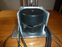
The fifth and sixth sides of the aluminium box around the two transformers should be thick aluminium.
Imagine putting your battery powered pocket radio inside a biscuit tin.
Put on the lid. No radio signal to amplifiy. Take of the lid (sixth side) and the radio plays. Orient the open sixth side towards and away from the radio transmitter. The radio still plays. The energy still gets in through the opening no matter what direction it is facing.
The same applies to the box around your transformers.
Do not add bypass caps across the PSU smoothing.
Have a good look at the amplifier PCB and see where each section draws it's current from. Does this current draw influence what happens to other sections on the PCB? This analysis should indicate where and how many and how much local decoupling should be added to the PCB.
The fifth and sixth sides of the aluminium box around the two transformers should be thick aluminium.
Imagine putting your battery powered pocket radio inside a biscuit tin.
Put on the lid. No radio signal to amplifiy. Take of the lid (sixth side) and the radio plays. Orient the open sixth side towards and away from the radio transmitter. The radio still plays. The energy still gets in through the opening no matter what direction it is facing.
The same applies to the box around your transformers.
Hi Andrew, thanks for the reply, your type of comment is just what I need.
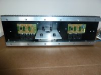
The screening around the two transformers is "U" section profile that I came across and it's internal dimensions were good for the size of transformer. The open rear will be enclosed by the back panel of the chassis and the top will be covered by a fine mesh metal sheet that I will use to make the top cover of the amplifier.
I have attached a circuit diagram and have marked where I have broken the track to add the separate supply for the front end, as you can see the +ve rail is broken between Q109 and R122 and the -ve rail between Q110 and R123. The output transistors and the driver transistors are fed directly from the main filter capacitors ( 47,00uf per rail ).Should I fit decoupling capacitors to the drivers?
The "front end" of the PCB is fed from separate rectifiers and 10,000uf per rail.
I hope it was a good idea to run the front end from a separate supply ( same transformers ). Measuring AC with a DVM across the filter capacitors for the output stage I get aprox. 80mV and across the filter capacitors for the front end I measure aprox. 10mV. In my simplistic mind I can only think its not a bad thing.
Thanks
Alan
Attachments
alibear
I also run the front-end from the same transformer feeding different bridge and caps, and I have no hum or other problems at all.
I do feel though that you have mounted your output transistors too close together, and also noted before that the KSA50 sounds much better when biased up quite high. Say around 1.9A per channel. But on the other hand your current heatsink arrangement will never be able to handle that much heat, so biasing lower is all that will work for you now.
Other than that: very neat build.
Last edited:
Hi Henryve, thanks for your comments. I built this version of the KSA50 ( let's call it a KSA25) with real world considerations in mind. I have made this amplifier in several different forms using higher rail voltages and both fan cooling and enormous passive cooling. The fan versions were always noisy no matter how slow I tried to run the fans and the physical size of passive heatsinks with 40volt rails was prohibitive in terms of using the amplifier in a average sized living room, plus all that heat was uncomfortable.
Using 26volt rails I have biased it at 1.4A giving me 30W class A with a voltage swing of 22v into 8 ohms and 70W dissipation per chanel. The heatsinks I am using reach aprox50C with ambient at 25C. The finished size is 310mm wide x 400mm deep x 140mm high. This is much more a "liveable" size for me personally.
Could you explain why increasing the bias will make it sound better? I think that the 22v swing at 8 ohms is the maximum with rail voltage I am using.
The output devices are mounted on the printed circuit boards that were supplied with the amplifier PCB. These were obtained from a group buy on DIY Audio from a respected company ( not eBay) So far I have had no problem with the layout.
As mentioned previously I have compared this amplifier to other class A amplifiers I have built and am more than happy with the results.
alibear
The higher you bias the amp, the longer it stays in Class A when increasing the volume.
The higher you bias the amp, the longer it stays in Class A when increasing the volume.
A speaker can and will draw different currents for the same peak voltages.
If the peak current exceeds the ClassA limit the amplifier will transition into ClassAB. If the output stage is not set to optimally biased ClassAB then that excursion out of ClassA will be at higher distortion.
These excursions beyond ClassA can occur without entering voltage clipping.
If the way you operate your amplifiers causes them to leave the ClassA region, then you may hear an improved sound quality (reduced distortion) by increasing the Output Bias Current.
^^ Andrew's explanation is the more technically complete version. Mine is the lazy to type and explain myself version.
But engineering is a discipline based on creating a solution given certain criteria and limitations, and you have done what is needed given your limitations. So sit back and enjoy.
But engineering is a discipline based on creating a solution given certain criteria and limitations, and you have done what is needed given your limitations. So sit back and enjoy.
Hi Henryve and Andrew, thanks for your reply. I understand your explanation regarding loudspeaker impedance and bias current. As I mentioned before I biased for the largest output swing I could achieve with my rail voltage into 8Ohms. I can see now from your explanation that it would be better to use a higher bias even though I could never achieve the voltage swing it would give.
The question now is, how high should I bias? Is it a case of using the maximum bias that the heatsink can deal with, obviously taking into account the current that the power supply can give. Or any other way?
Thanks
Alan
The question now is, how high should I bias? Is it a case of using the maximum bias that the heatsink can deal with, obviously taking into account the current that the power supply can give. Or any other way?
Thanks
Alan
did you give this part of my comment any weight in deciding that your bias was wrong?you may hear an improved sound quality (reduced distortion) by increasing the Output Bias Current.
Or did you just ignore it?
Hi Andrew, I may have misunderstood / misread / unable to comprehend your post but I would certainly not ignore it.
After reading the post from henryve and yourself it appeared clear to me that a higher bias would be a good thing, and whilst I am still in the "building" stage perhaps I could accommodate a larger heatsink to allow me to do this.
I am not sure that the amplifier would be operated past it's class A current as it stands at the moment, but extra current availability would be an advantage.
Have I misunderstood, or not thinking enough.
thanks
Alan
- Home
- Amplifiers
- Solid State
- Krell KSA 50 PCB