Hi PinkMouse
Just fired up my main + driver boards yesterday through my old Mordaunt-Short Classic 20s. Sounded damn good, even my wife was surprised at the sound quality, and I have not yet attached the output boards yet. Almost there.
Just fired up my main + driver boards yesterday through my old Mordaunt-Short Classic 20s. Sounded damn good, even my wife was surprised at the sound quality, and I have not yet attached the output boards yet. Almost there.
Glad you like it. 🙂
Mine is in bits again. Chassis got damaged, and I nicked the PSU for another project. But it will be reborn! 😀
Mine is in bits again. Chassis got damaged, and I nicked the PSU for another project. But it will be reborn! 😀
Thanks for the heads-up about the KSA boards on ebay. I think I'll make my own though. I am always up for a challenge. I would like a particular layout to fit the heat sinks I want to use.Hi,
This gentlemen on e-bay has a pcb suitable to make a very nice clone.
High Power Pure Class A Amplifier PCB KSA100 | eBay
I did purchase a set and I must say it is very well made. It would be probably easier than making your own. If you want more pictures or info just PM me
Cheers,
Eric
BTW
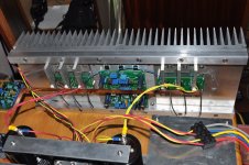
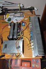
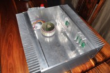
This is my current test setup. I am about to wire up the outputs to the busbar and then I am ready to bias this channel. The other channel is still in my workshop for final metalwork.
[image]http://www.diyaudio.com/forums/attachment.php?attachmentid=326980&stc=1&d=1359450395[/image]
[image]http://www.diyaudio.com/forums/attachment.php?attachmentid=326981&stc=1&d=1359450395[/image]
Regards
Attachments
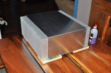
Nice engineering! Thought about the rest of the case yet?
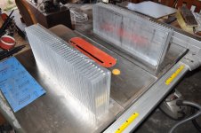
Yup, in progress. Some more drilling needed for binders and sockets etc, and front panel still in the works. Hard work this if you only use tablesaw, standing drill and a set of files.
Attachments
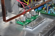
Looks really nice - nice detail work on the output section with the profiles for the Caddock resistors also!
May I ask which output devices did you use - and did you match them?
Best regards
Hans
May I ask which output devices did you use - and did you match them?
Best regards
Hans
I used On Semi MJL3281/1302 pairs. Not matched. Matching not really important on the KSA50, although it does come from the same 25 unit clip.
Last edited:
Just as a follow-up, I'll be using the following transistors in the various stages:Thanks for the heads-up about the KSA boards on ebay. I think I'll make my own though. I am always up for a challenge. I would like a particular layout to fit the heat sinks I want to use.
LTP - 2SA1016 / 2SC2362
VAS - KSA1381 / KSC3503
Driver - 2SA1306B / 2SC3298B
Output - MJ15003 / MJ15004
Hi all, glad to see this thread has sprung back to life and really happy that Pinkmouse is still on the scene.
I have been constucting a KSA50 for a long time now, along the way I have altered my design concept several times ( not the circuit, but the cooling and power output ) I started with +- 25volt rails and about 1.5A bias and passive cooling, giving about 25W. This was OK but I ran into problems with heat, I was only dissapating about 70W per channel, but the sinks got very hot as did the rest of the amplifier internals.
Henryve, how big are your heatsinks, the case looks very professional. Mine were 400x150x40 each side.
I then used a heatsink tunnel almost identical to an original KSA50 with a Papst fan and rails of +-33v. Cooling was much better, but I was not happy with the chassis layout.
I am now on the third incarnation and I hope I get it right this time. I have collected most of the parts I need so will start putting it together soon (I hope ) I have chosen a physical layout very similar to the original KSA100. I am now using 2x 30V 500VA transformers, 2x40,000uf per rail, 2x heatsink tunnels (same as Krell but about 150mm high) 2x Papst 12V fans, 2x Jans PCB's, case is ex computer server, bit big, hope the wife understands.
I will post some pics of the parts hopefully tomorrow before I start assembly.
Pinkmouse, now the rails will be approx +-42V do I need to change any component values on the PCB. I seem to recall that R122 and R123 should be increased from 100 ohm to 150 ohm ? Thanks for the advice about regulator for front end, have you a circuit that would be good for this?
Thanks
Alan
Gosh, I can't remember if I changed R122/3 or not, ( I was running on 42V rails as well). As for the regs, one of the Maida type ones should be fine.
alibear
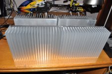
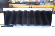
My heatsinks (each side) is 510mm (D) x 200mm (H) x 75mm (W). The base part of my heatsink profile is 15mm whilst the fins are 60mm. My fin spacing is about 13.5mm. I recon it should be enough, though not for today because today our Ta = 38 deg C, so I don't think any passive will make it today.
I used 150R for R122/3.
Hi, thanks henryve and Avwerk for info on R122/3
I have attached a couple of pics of my first attemt at the KSA. I was using 25V rails, aiming for about 25W per channel and dissapating about 70W per channel in heat. The chassis sides and bottom were 10mm aluminium and the sinks were aprox 400X150X40mm.
Even with this low dissapation the sinks and chassis became very warm. I have no exact temperature but I think about 55C using the finger test. I realise that the output devices would be OK but it was the rest insde the chassis, transformers, caps, etc that I was concerned about. That is why I have now gone to active cooling
I have used two heatsink tunnels as per the original KSA100, but they are taller, aprox 140mm and two Papst 12V fans. This may be over the top for a KSA50 but I can run 42V rails at almost 2A bias and can quite comfortably keep my finger on the output devices (8 per channel). The sinks will be issolated from the chassis so everything else should be fairly cool. I have only ran in test conditions, eg amplifiers running outside the chassis, lot of work to do yet so I will keep my fingers crossed.
Alan
Attachments
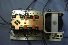
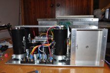
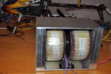
My barrierstrips arrived today so I can now complete the wiring for my PSU module. Pics of the power module attached.
Some info on my PSU. 2 X 500VA transformers with 2 X 30V secondaries each. This is fed on each transformer to 4 rectifier bridges. One set of bridges feeds 2 X 10000uF 63V Epcos Sikorel caps which will be used to power the main and driver boards. The second set of bridges feeds 2 X 55000uF 63V Alcon caps, and this will be used to power the output transistors. The Alcons are cheapies from India, and I hope to later replace them with Epcos caps, though not Sikorels. The big Sikorels are priced completely out of my wallet, so I will go for the cheaper ones.
Good caps are not cheap, so for my KSA100 clone I am already starting to collect caps. For that project I am aiming to use the Vishay Sprague Powerlytics, which goes for over $100 each.
Attachments
Alan
My experience with the el-cheapo 'by-pass' caps you seem to have used in your Krell PSU has been that they can be extremely sharp and two dimensional sounding. At first they might impress but on the long term it becomes tiresome.
Still your workmanship s very impressive. In fact all the latest clones are beginning to look like pieces of audio art.
Regards
Jozua
- Home
- Amplifiers
- Solid State
- Krell KSA 50 PCB