low voltages
I don't remember anything else being an issue, fortunately since you are lowering the voltage things will tend to fail safe, and the amp may sound nasty or have no sound at all, but it should fail safe.
Which brings up an interesting point; the distortion characteristics may change as the voltage is lowered and it is quite possible/likely that other adjustments would be needed for optimal performance at any given voltage.
I know the amp works with rails as low as +/-10v with the CCS, so I think you will be fine at +/-22v.
HTH
Stuart
Johnm,
Thanks for the great offer, I would like to take you up on it but I insist that I pay you for them. At the moment I can't email you as I'm under moderation ( new member ). How can I contact you to make arrangements?
Thanks
Alan
Thanks for the great offer, I would like to take you up on it but I insist that I pay you for them. At the moment I can't email you as I'm under moderation ( new member ). How can I contact you to make arrangements?
Thanks
Alan
No honestly I don't want any money. I've had a few generous free items from people on this forum over the years, so I'm just keeping the 'tradition' alive and well 🙂 Karma and all that 😛
I have a pair of the boards, plus the Krell Clone badge and a few transistors so you're welcome to all that. Bought them all about 5 years back now and already have 5 amps so they're just completely superfluous lol!
PM me on private23 AT hotmail DOT co DOT uk
(will delete the email addy after you've got in touch).
Cheers,
- John
Why not design your own PCB ?
There are loads of cheap/free/expensive pcb layout packages out there.
There are loads of cheap/free/expensive pcb layout packages out there.
Re: My hot KSA-50 clone
While a lot of people here have made the Krell clones, I don't recall seeing that one and the components and board don't look quite right....And the link you posted does not indicate that the same board was implemented by a 'member' here, as far as I can tell by looking at the pics (which appear not relevant). What do you mean 'suggested bias'? The bias is as suggested on the krell clone wiki.
What are your DC voltages and give us a close up of those boards!
Yes, and are those pics accurate? Is there STILL a pen under that transformer? Why?
I do not think that anyone here made that thing...but I could be wrong. I think someone may have claimed to build that based on something here but it appears to be way off.
But again, I could be wrong.
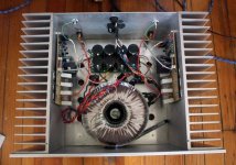
audiophile321 said:Still looking for the correct schematic and suggested bias for this version of the KSA-50 clone. I'd like to talk to the builder if he sees this. I've attached a pic of the interior.
Thanks in advance for any help.
Jim
While a lot of people here have made the Krell clones, I don't recall seeing that one and the components and board don't look quite right....And the link you posted does not indicate that the same board was implemented by a 'member' here, as far as I can tell by looking at the pics (which appear not relevant). What do you mean 'suggested bias'? The bias is as suggested on the krell clone wiki.
What are your DC voltages and give us a close up of those boards!
Yes, and are those pics accurate? Is there STILL a pen under that transformer? Why?
I do not think that anyone here made that thing...but I could be wrong. I think someone may have claimed to build that based on something here but it appears to be way off.
But again, I could be wrong.
Hot running amp
Hi lgreen,
The seller on audiogon did tell me that the amp was build by a member here, but who knows? I've been crazy busy for the last week and haven't had any time to dig in to this amp. I will try to upload a close up of one of the boards tonight and check the supply rail voltage.
The amp was damaged by the shipper and the back panel got caved in which isn't the end of the world as I'd like to upgrade the RCAs and speaker terminals any way. The toroid isn't tightly mounted and I assumed this was from rough handling by the shipper but that may explain the pen in the seller's pic I'd attached.
The seller didn't include the pen with the amp, should I feel jipped? 🙂
It could be, I've read about Tim here, but that's not who my seller said built it. I know the alleged builder's moniker but I'm not going to post it. I'm still under moderation, when I am able to I'll email him privately.
Jim
Jim
Re: Hot running amp
Well, the case seems ok...but maybe not for a ksa-50. Lets see some pics when you have a chance.
audiophile321 said:Hi lgreen,
The seller on audiogon did tell me that the amp was build by a member here, but who knows? I've been crazy busy for the last week and haven't had any time to dig in to this amp. I will try to upload a close up of one of the boards tonight and check the supply rail voltage.
The amp was damaged by the shipper and the back panel got caved in which isn't the end of the world as I'd like to upgrade the RCAs and speaker terminals any way. The toroid isn't tightly mounted and I assumed this was from rough handling by the shipper but that may explain the pen in the seller's pic I'd attached.
The seller didn't include the pen with the amp, should I feel jipped? 🙂
Well, the case seems ok...but maybe not for a ksa-50. Lets see some pics when you have a chance.
Ksa-50
Well since there are only 4 boards like that...I would say someone dissassembled my 4 channel Krell ...🙁
Wonder what happened to the case...transformer...heat sinks..
Check here for info:
http://www.diyaudio.com/forums/showthread.php?postid=949974#post949974
Post #6748
Err...and where are the other half of the Power supply caps ?
Hot KSA50 measurements
I finally got to check some voltages in my hot amp and here's what I found:
Supply voltage is +/- 36VDC
The emitter resistors are .47 ohm and the average volt drop is 330mv and closely matched.
There are 3 pairs of output transistors per channel so if my calculations are right the total dissipation at idle is 153 watts per channel.
This all seems correct to me so I'm thinking the heat sinks aren't large enough to safely run at 50 watts class A.
Any thoughts?
BTW, measurements were taken after the amp had been on for 15 minutes and temperature had stabilized.
Hot amp
Hi zlast,
The output transistors were 165F on the right channel and 185F on the left, the heat sinks as I recall were about 20 degrees cooler. Also of concern, at least one of the right driver transistors is getting to 200F (I can't get a good measurement on the lower one)
Jim
Hi zlast,
The output transistors were 165F on the right channel and 185F on the left, the heat sinks as I recall were about 20 degrees cooler. Also of concern, at least one of the right driver transistors is getting to 200F (I can't get a good measurement on the lower one)
Jim
Hi everyone,
I have two torroids that I will be using for my power supply, they have centre tapped secondaries of 18 0 18volts at 6.3amps per winding ( I don't require 50 watts, so I'm trying to build a ksa 25 ).My question is I have seen several designs for the Krell supply, for each channel some use one bridge rectifier with the centre tap of the windings taken to 0Volts and some use two bridges ( one for each winding ) with the -ve of one bridge and the +ve of the other bridge going to 0Volts. I have the option to use either, which is the best way, and what advantages / dissadvantages are there
Thanks
Alan
Re: Hot amp
why are L & R operating at different temperatures?
The driver dissipation is dependent on the Re value between the drivers.
To reduce driver temperatures either increase their heatsink or increase the Re.
Hi,audiophile321 said:The output transistors were 165F on the right channel and 185F on the left,.......... Also of concern, at least one of the right driver transistors is getting to 200F
why are L & R operating at different temperatures?
The driver dissipation is dependent on the Re value between the drivers.
To reduce driver temperatures either increase their heatsink or increase the Re.
I would suggest that the maximum quiescent current you should draw from your 6.3A transformer is <=1.6Aalibear said:....... centre tapped secondaries of 18 0 18volts at 6.3amps per winding ( I don't require 50 watts, so I'm trying to build a ksa 25 ).My question is I have seen several designs for the Krell supply, for each channel some use one bridge rectifier with the centre tap of the windings taken to 0Volts and some use two bridges
Allow about 50mA for the voltage amp stage, another 100mA for the drivers, that leaves about 1.45A of bias for the output stage.
2.9Apk of ClassA current is probably going to perform quite well.
For these lower powers you should find that a single bridge rectifier will work well with a small heatsink.
Build two monoblocks to avoid any problems with channel to channel common grounds.
BTW,
for a 3pair output stage using Re=0r47, 0.22Vre gives about 1.4A bias
- Home
- Amplifiers
- Solid State
- Krell KSA 50 PCB