http://www.diyaudio.com/forums/attachment.php?s=&postid=518822&stamp=1101232248
Here's that attachment from previously!
It's not the "final" version....(quite old)
Here's that attachment from previously!
It's not the "final" version....(quite old)
Sorry for the differences between the schematic and parts list...
Sadly... At my work I have a BOSS that insists that I do some work for him too, since he is paying me full salory 🙄
So does anyone have a suggestion for how to slow down the earths rotation, so I can get 48 hours a day ????? 😀
I try to get the mismatch fixed and uploaded today 😉
Sadly... At my work I have a BOSS that insists that I do some work for him too, since he is paying me full salory 🙄
So does anyone have a suggestion for how to slow down the earths rotation, so I can get 48 hours a day ????? 😀
I try to get the mismatch fixed and uploaded today 😉
Hi Ipanema-
Please send me your address. Apparently my return emails are not reaching you.
Thank you in advance,
Troy
Please send me your address. Apparently my return emails are not reaching you.
Thank you in advance,
Troy
Chassis
I may be up for a chassis group buy. I've got a heat tunnel and will be using a fan like in the orig. KSA50. If the chassis can support this I'd be interested.
I may have custom enclosures made for my KSA-50 and if so it is always cheaper to have more than one made. Chassis GB for the KSA-50?
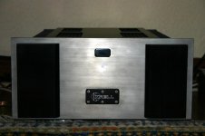
Here is a picture of my gain clone chassis I had made.
rabstg has attached this image:
I may be up for a chassis group buy. I've got a heat tunnel and will be using a fan like in the orig. KSA50. If the chassis can support this I'd be interested.
I just caught this in another thread....
http://www.diyaudio.com/forums/showthread.php?threadid=45352&perpage=10&pagenumber=2
Don says to......
"Be cautious of the source of the schematics you intend to use. I have seen several where the compensation capacitors are given as 10x the actual value (i.e. 390pF instead of 39pF). There is one on the internet that has added SOA protection to the outputs which is not necessary. All of the later vintages mount the bias transistor on the driver board, not the output stage. Because of the class "A" operation, this is possible. I have posted the correct schematics on my page:"
So I was wondering if anyone verified that C-105/106, and C107/108 are the correct values... they do seem a bit high to me. Wish I could do the calculations, perhaps someone else here already has or could.....? The pre 1983 schematic on Don's Krell site has a 470 pf for C-101 instead of a 680 pf.........
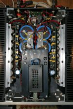
My progress as of tonight in the photo below. Will order semi's tommrrow. Heat sinks are already on order. Have power supply already.
Thanks!
Mark
http://www.diyaudio.com/forums/showthread.php?threadid=45352&perpage=10&pagenumber=2
Don says to......
"Be cautious of the source of the schematics you intend to use. I have seen several where the compensation capacitors are given as 10x the actual value (i.e. 390pF instead of 39pF). There is one on the internet that has added SOA protection to the outputs which is not necessary. All of the later vintages mount the bias transistor on the driver board, not the output stage. Because of the class "A" operation, this is possible. I have posted the correct schematics on my page:"
So I was wondering if anyone verified that C-105/106, and C107/108 are the correct values... they do seem a bit high to me. Wish I could do the calculations, perhaps someone else here already has or could.....? The pre 1983 schematic on Don's Krell site has a 470 pf for C-101 instead of a 680 pf.........
My progress as of tonight in the photo below. Will order semi's tommrrow. Heat sinks are already on order. Have power supply already.
Thanks!
Mark
Attachments
neychi:
Updated PCB-layout will be made and uploaded when we are sure that there are no further corrections 😉
Updated PCB-layout will be made and uploaded when we are sure that there are no further corrections 😉
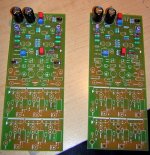
Got my boards today, i love them, they look excellent!! I might start with semi's (i know, not a good idea) but it's what i've got here to install now, so i might go with it 🙂 I'm doing one tonight, at least placing the parts, maybe not solder (as i'm waiting on 2% silver solder, it's worth at least 400 points towards better sq!!! lol)... But having a go with placement....
What heatsinks do we need on the drivers/bias etc???
Aaron
What heatsinks do we need on the drivers/bias etc???
Aaron
NUTTTR said:Got my boards today Aaron
Wow, Australia in 7 day's!!!
If anyone has NOT gotten their boards by now please email me.
stgrab@yahoo.com
Has anyone received damaged boards? All shipments were insured.
NUTTTR,
That old list is more accurate than the most current posting.
Since you are also building with TO3's and eliminating the "modern improvements", maybe we can get you and others who wanted only to replicate the original KSA 50 to share info on what parts to leave off this board.
Prosit
That old list is more accurate than the most current posting.
Since you are also building with TO3's and eliminating the "modern improvements", maybe we can get you and others who wanted only to replicate the original KSA 50 to share info on what parts to leave off this board.
Prosit
Hi All-
I "suggest" and this is only a suggestion, that you snap off the output boards before you start component assembly...
It can be done post installation, I just find it a lot easier and less stressful when the boards do not have parts that can be damaged.
I "suggest" and this is only a suggestion, that you snap off the output boards before you start component assembly...
It can be done post installation, I just find it a lot easier and less stressful when the boards do not have parts that can be damaged.
Hi!
So what shall we do about this capacitors (C-105/106, and C107/108)? 39pf or 390pF and 470pF or 680pF?
Dean🙂
So what shall we do about this capacitors (C-105/106, and C107/108)? 39pf or 390pF and 470pF or 680pF?
Dean🙂
NUTTTR said:Got my boards today, i love them, they look excellent!!
Are you in Melbourne ? Maybe we can run your KSA50 -when finished- against my KMA200 clone (demoted to KSA100 bias wise, but with full 16 MJ15003/4 pairs per channel) sometimes ...
Bratislav
Attachments
I'm not 100% sure on the values of those caps, i'm starting to question after looking through a few ksa-100 schematics and ksa-50 ones... The "390pf" capacitor is (in my mind) serving a different purpose in one of the schematics i've got...
Have a close look!
Aaron
Have a close look!
Aaron
Attachments
Bratislav said:
Are you in Melbourne ? Maybe we can run your KSA50 -when finished- against my KMA200 clone (demoted to KSA100 bias wise, but with full 16 MJ15003/4 pairs per channel) sometimes ...
Bratislav
I'm in sydney 🙁 That makes it difficult, but i do love the design in your amp! Looks excellent!
Hi All-
Is anyone out there not “thermally challenged” as I am and have time to answer a question?
The question is how long does the extrusion need to be for a single channel?
I am planning on building 3 mono block KSA-50 Klones with a heat sink extrusion from the following page.
Item # MM10332. Fourth one from the bottom of the following page.
http://www.mmmetals.com/pages/extru...back_heatsink_aluminum_extrusion_4_and_up.htm
Here is the actual link to the item:
http://www.mmmetals.com/extrusions/drawings/mm10332.jpg
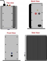
I will be using the heat sink as one side of the amp, the other side will be ¼” thick, the front will be ½”, and all other sides will be 1/8” thick Aluminum.
Below is basic example:
EDIT: Note drawing is NOT to scale.. Size will depend upon the answer to the above question.
And thanks again for your feedback.
Is anyone out there not “thermally challenged” as I am and have time to answer a question?
The question is how long does the extrusion need to be for a single channel?
I am planning on building 3 mono block KSA-50 Klones with a heat sink extrusion from the following page.
Item # MM10332. Fourth one from the bottom of the following page.
http://www.mmmetals.com/pages/extru...back_heatsink_aluminum_extrusion_4_and_up.htm
Here is the actual link to the item:
http://www.mmmetals.com/extrusions/drawings/mm10332.jpg
I will be using the heat sink as one side of the amp, the other side will be ¼” thick, the front will be ½”, and all other sides will be 1/8” thick Aluminum.
Below is basic example:
EDIT: Note drawing is NOT to scale.. Size will depend upon the answer to the above question.
And thanks again for your feedback.
Attachments
- Home
- Amplifiers
- Solid State
- Krell KSA 50 PCB