So in summary - don't be cheap with the components at this point and shell out a few extra bucks to put in a separate ps for the fans 
Lgreen - I like your thermal (Normally Open) switch idea. Would it be impractical to mount one of those on each sink (4 total) and have the fans independantly wired back to a shared fan/ relay supply? I don't expect there to be much variance in temp between the 4 sinks unless something were to go awry.
Thanks all!
~Brad
googler said:Lgreen - I like your thermal (Normally Open) switch idea. Would it be impractical to mount one of those on each sink (4 total) and have the fans independantly wired back to a shared fan/ relay supply? I don't expect there to be much variance in temp between the 4 sinks unless something were to go awry.
Thanks all!
~Brad
Thanks I'm just winging it over here.
Impractical? Hmmm.....
Let me see if I understand your implementation- you want to use 4 NO thermal switches, and if any single one of them shorts (meaning there is heat), you energize a relay that keeps all your fans in the "on" condition? Should be easy except where do you get the voltage to drive the relay? You either need a third power supply or you will have to wire your small power supply to be "always on" such that there is always the relay drive voltage across the small power supply which is fed to your 4 thermal switches so if any one clicks closed a relay actuates and feeds voltage to your fans. Here "always on" means that its impossible to turn off this smaller power supply, though you could put a small switch somewhere for manual deactivation. If you have 4 fans it could be set up to actuate only the fan associated with the hot sink, though why not cool everything? Your choice.
Here it would be very smart to use a 12VDC relay and 12VDC fans, so you can reduce the fan voltage with a divider or regulator after the relay in order to not affect the ability to actuate the relay in the first place. Good stuff.
Are 4 thermal switches necessary? These are expensive, like $4-$6 each. If you look at my web site (below) there is a graph of the output heat sink temperatures. You see that the L+ and R+ sinks tracked closely, probably off only becuase the bias on the left channel was slighlty off from the bias on the right channel by a small amount. Is it possible or likely that the + and - sinks of the same channel can be at different temps? Maybe Jacco, Pinkmouse, Stewart or AndrewT can answer this, but I'm not sure its likely in theory. Plus unless you have live sinks you will stagger the transistors so a single sink has both + and -.
but this is diy so overkill is definately allowed...
googler
Not that this is the best-- but I used a Dell laptop power supply of 19 volts to run a IMB 4" 48 volt fan. It's small size works out quite well
Turn on with these fans requires at least 15/16 volts and 19 is about right for flow and low noise combined. Right up there with the best low noise Pabst's
Even though it's a switching supply (bad for noise issues) I see no anomolies on the scope to indicate anything being introduced into the circuit.
I have it switched seperately with a red led so I can turn it on/off.
Works fine now, but will come up with something more automatic later on when I can find more time!
Regards
David
heatsink temps...
AFAIK...for each channel, at idle all the current goes through both banks of transistors, so each bank will have the same total dissipation, assuming all (voltage on rail, airflow, etc) else equal
Possibly you could see one transistor hogging more current and getting a little warmer than the others, but my tests indicate this is a very small effect (<5% difference), even with transistors from different batches. You could measure to be sure, check each emitter resistor voltage in turn. Unless you hand selected the emitter resistors to be identical, the chances are they are the limiting factor.
This situation is peturbed with the amp playing, but unless the output waveform were very consistently asymmetric, ie not averaging to zero over a minute or so, the banks should still end up at the same temp, and overall should actually be getting cooler as more power is delivered to the load.
Personally I am using one sensor for one bank of each channel, and have it set up to disconnect power from the amps if the heatsink temp reaches 75, since they are external heatsinks, don't want to fry the cat...
HTH
Stuart
Good point
Stuart makes a good point.
Most people use one of these (normally closed) bimetal thermal switches in-line with the transformer primary and mounted on a major heatsink in order to turn the amplifier "off" (disconnect the xformer primaries) should the heat sink exceed the threshold (say 75, 65 or 60 C for example) of the switch which causes the switch to open up.
These switches have very low resistance and have no trouble passing in many amps of current to your amp in their closed position.
 !!
!!balanced front end...
...it's actually pretty easy. There are 2 obvious routes, well three if we include a high quality transformer...
1) We can use an opamp design to precede the amp we already have. Designs for this are a dime a dozen, and therefore not that interesting to me.
2) We can use the LTP that is part of the design, basically very simple, we can probably build it as a simple hack to the current boards. Not the highest technical performance, but all it'll cost is a couple of resistors and maybe some high quality caps. The most obvious example of commercial amps that have done this are the alephs, as far as I know the results were very good.
I've never worked with balanced inputs, what are the normal input impedances we'd want. What is considered a good noise level, common mode rejection ratio etc.
Lastly I'm not sure how I'd test the result of my/our endeavours, since nothing else I have is balanced...
Stuart
Hmm,
The answers to most of your questions are well above me. Regarding balanced stuff, My own experience only includes alephs. They sound worlds better driven balanced in my opinion..Maybe/hopefully someone more knowledgable will chime in.
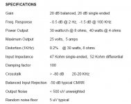
I'd be willing to take mine apart and give a decent idea a try. I'm just not smart enuff yet to come up with the decent idea I am not really into sticking opamps or traffos into it, however.
attached are some specs from an aleph manual
Thanks
The answers to most of your questions are well above me. Regarding balanced stuff, My own experience only includes alephs. They sound worlds better driven balanced in my opinion..Maybe/hopefully someone more knowledgable will chime in.
I'd be willing to take mine apart and give a decent idea a try. I'm just not smart enuff yet to come up with the decent idea
I am not really into sticking opamps or traffos into it, however.attached are some specs from an aleph manual
Thanks
Attachments
You wouldn't be aiming for post nr7000, would you?OMG! The thread was at the bottom of Solid State page 4 !!

Hi,
a DC output offset will make the +ve & -ve heatsinks run at different temperatures.
The Klone can be set up for DC gain =1 and with DC blocking on the input. With this set up any significant offset indicates the amp has gone faulty and irrespective of sink temperature should be switched off (either manually or automatically).
If the Klone were set up with either or both the DC blocking caps omitted then the DC at the output could be substantial and yet still operating correctly.
In this latter situation, let's take a few numbers.
Iq=1.9A, Vrail=+-37V Rload=8ohm
DC offset = 8V, giving 1A of bias into the 8ohm load, which is equivalent to 8W of heating in the Bass Driver.
The output devices now have unbalanced Vce of 29V & 45V.
However, the Ic of the two halves is also unbalanced (just as it is when swinging an AC signal) the 29V half will have 2.4A and the 45V half will have 1.4A ( the net difference flows to the load).
The power in the two halves will be 70W (29*2.4) and 63W (45*1.4).
This +-5% variation in upper and lower half dissipated powers is relatively innocuous but will be detectable by switches or thermometer.
thats probably a great start...
...NP seems to like balanced things, so my guess is this is a good set of figures for a domestic piece of equipment.
So I'm using the aleph balanced input as my inspiration. Since we are using BJTs instead of mosfets there might need to be a few adjustments, but I'm thinking it will be more similar than different...
Stuart
is there any reason a bank of parallelled 4-pole 15,000 uF caps wouldn't work as well as the original single 40,000uF configuration? might take up less space. a lot of things i've read about PSU design suggest that multiple small capacitors in parallel are more effective than single large ones because they can drain and charge more quickly. is this of consequence in a class A design? i might try it if i decide not to go with the capacitance multiplier.
bikehorn said:is there any reason a bank of parallelled 4-pole 15,000 uF caps wouldn't work as well as the original single 40,000uF configuration? might take up less space. a lot of things i've read about PSU design suggest that multiple small capacitors in parallel are more effective than single large ones because they can drain and charge more quickly. is this of consequence in a class A design? i might try it if i decide not to go with the capacitance multiplier.
No problem, a bank of those caps would be as good or better than a big cap. I used 10 x 15,000 uf in my LM4780 amp.
thanks, i thought so. i just wondered if this particular amp had some preference for huge electros. i think i will first try the capacitance multiplier and see how it sounds....imagine how much less space it would take up in the chassis!
also, there is a large fan tunnel on Apex Jr that i am tempted to buy. it's built to accomodate 10 TO-3 per side and will fit a 120 mm fan...not to mention it's 12 inches long. think it'll be enough with both channels on it?
also, there is a large fan tunnel on Apex Jr that i am tempted to buy. it's built to accomodate 10 TO-3 per side and will fit a 120 mm fan...not to mention it's 12 inches long. think it'll be enough with both channels on it?
bikehorn said:also, there is a large fan tunnel on Apex Jr that i am tempted to buy. it's built to accomodate 10 TO-3 per side and will fit a 120 mm fan...not to mention it's 12 inches long. think it'll be enough with both channels on it?
I've seen that heatsink before, note that the picture shows only holes for 8 per side not 10 per side.
I believe others have used this sink for the Krell but if you were to ask me, I would guess is that this would be just big enough for stereo 50WPC class A with 4 TO-3 devices per channel, fan running full tilt or almost running full tilt.
also, there is a large fan tunnel on Apex Jr that i am tempted to buy. it's built to accomodate 10 TO-3 per side and will fit a 120 mm fan...not to mention it's 12 inches long. think it'll be enough with both channels on it?
My friend is using one of those for his along with two of Steves 230V papst-fans but he hasn't fired it up yet. And to confirm what lgreen said, there holes for 8 per side (I have one unused tunnel in my closet).
i don't really need anything more than 50 watts, i am currently pushing 35 and using fairly efficient speakers...but i like the idea of adding an extra pair of outputs on each channel to reduce stress per device. if i keep it biased for 50 watts, will i have more heat with 3 pairs per side vs. 2 pairs?
more heat? nope...
...more devices on the same heatsink makes each of them a little cooler. It actually reduces the total thermal resistance of the junction between the active devices and the heatsink.
Perhaps counter intuitively, with all else equal, the heatsink will be a little hotter, but the transistors will be a little cooler...
IMHO, within reason, the same total bias spread over more devices is better, the gain of the output stage will be probably be higher, since each device is doing less, the emitter resistors can be a little higher, encouraging better sharing, and providing better local degeneration...
Stuart
- Home
- Amplifiers
- Solid State
- Krell KSA 50 PCB