I couldn't get hold of the Japanese parts in the UK, and others said they hd difficulty sourcing them as well.
Hi,
is the pinout of the 2SA/C the same as the MPSA? i.e. bce.
Then use the 2SA/C if you can find them economically. They have
better gain, better bandwidth, better noise, better gain linearity, better Cob, worse voltage rating, worse Ic, worse power dissipation. 2SA/C wins hands down for the relevant specs in this application.
However some would say that in a good circuit design component specification variations are designed out of the product performance specification. The end result may be that both types sound the same.
I found no audible difference when I finally tested them, but as always YMMV. The things that did make a positive difference were the output trannies and increasing the C102/3 capacitance, though the latter did cause a turn on thump, as you might expect.
Pin out for the 2SC/A is different, but you can always bend the leads to fit and use a bit of sleeving on the legs to prevent shorts.
Pin out for the 2SC/A is different, but you can always bend the leads to fit and use a bit of sleeving on the legs to prevent shorts.
Before I hook up the big toroid to the briangt PSU boards, I just wanted to comfirm the wiring.
The 29V secondary wires (2x2) go 1 to +v and 1 to -v and the middle wire (0V) goes to the GND pad on each board
Correct?
Thanks,
Brad
The 29V secondary wires (2x2) go 1 to +v and 1 to -v and the middle wire (0V) goes to the GND pad on each board
Correct?
Thanks,
Brad
Hi,
as you said the +ve & -ve feeds go to the PCB.
The 0v common from the PSU goes to a Central Star Point that becomes your ground reference.
All other grounds and returns come back to this same point.
And use a light bulb in series with the mains supply to the PSU BEFORE you connect the amp.
Check your open circuit voltages and polarity.
Keep the light bulb in circuit and couple up the amp and switch on again.
Expect the bulb to glow gently due to some bias on the output transistors.
After you have checked your voltages again, remove the light bulb from the PSU supply and try again.
Now set up your bias in gradual steps and allow about 5 to 10 minutes between adjustments for the heatsink to warm up.
Krell upgrades
Well, I finally got fed up of my on/off switch only working 25% of the time, figured that it was time to change my soft start thermisters from 3 ohms to 10 ohms....what the heck, how about 20 ohms! Yeah!
My case does not come apart easily and I dreaded attempting it, so I cranked most of it out tonight but it will be tough to put back together. Kind of dreading that too.
Pics? here is one with the back panel off so I could put in a new switch, had to remove all the inputs and outputs and bias test points.
Installed some 1 uf Solen's on the big caps for snubbers, lets see how it works. Also rearranged the grounding, evened out the LEDs on all the rails.
Oh and the fan mounts are new improved, now painted yellow to match the other dividers in there.
i've finished one channel. I used MJ + MJE, all are original (i broke them to chek if it so). How it's sound. Almost great, dynamic bass, nice but a little to cold high tones. It's really great but not as great as my aleph 🙁. Aleph has this thing that makes you love it. Krell is only good worker nothing more. But i'll try it in stereo, maybe my judge is too early...😉
radzio222 said:i've finished one channel. I used MJ + MJE, all are original (i broke them to chek if it so). How it's sound. Almost great, dynamic bass, nice but a little to cold high tones. It's really great but not as great as my aleph 🙁. Aleph has this thing that makes you love it. Krell is only good worker nothing more. But i'll try it in stereo, maybe my judge is too early...😉
Hi radzio,
Cold highs huh. Doesn't sound like a Krell to me. The highs on both of mine are more on the warm side. A little colored maybe, but not cold at all. How high do you have the bias set? Also, did you compare the Aleph with only one side running to get a good comparison? No comparison to how an amps sound only playing one side of a stereo feed. Try feeding one channel on each amp and give them a mono feed so at least you are getting all of the information. The only Aleph I have built so far is an Aleph-X. It is nice sounding but you listen to it for a while and then switch over to the KSA50 and instantly you think, "Now yer talkin'!"
My Aleph is only running 17V rails so maybe that has something to do with it. Get the other side finished and give it time to break in and then see if it only feels like a working amp.
Blessings, Terry
PSU question revised
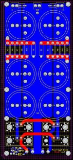
Alright, so I was looking at the wrong end of the PSU PCB (i thought that seemed a little too easy). There are 4 pads for hooking up power to the PSU board, AC0, AC0(with a line over it), AC1, and AC1 w/ line over it. I only have three wires (29V-0V-29V) and 4 pads... What do I plug in where?
Thanks,
Brad
Hi,
is Brian's PSU a dual rectifier type?
If so, it needs two separate secondary windings i.e. 0, 29 + 0, 29.
You can separate the centre tap but you need to open up the insulation and split the secondary at the centre tap. Wire in an extra connection from the secondaries then bring out the pair of wires that were the common (0Vac). One becomes 29Vac and the other becomes 0Vac.
Just before you go measure the secondary winding voltages and if needed add an extra turn to match them up exactly.
Re-wrap the windings to ensure no shorting once put to work.
Hi Andrew!
There are 2 rectifiers per rail. 4 total.
I guess running a jumper from where 0V is terminated to the other pad wouldn't work?
I'd rather modify the board or go point to point for the PSU than mess with the toroid. Its an epoxy filled monster.
So what, if anything, can I do to the board to make it work?
Thanks,
Brad
Attachments
BrianGT PS Board
If the board you have is the same as BrianGT sells for the Gainclone, he has pretty extensive instructions here.
http://www.briangt.com/nigc_kit-users_guide.pdf
http://www.briangt.com/nigc_kit-users_guide.pdf
If the board you have is the same as BrianGT sells for the Gainclone, he has pretty extensive instructions here.
http://www.briangt.com/nigc_kit-users_guide.pdf
http://www.briangt.com/nigc_kit-users_guide.pdf
googler
Just solder the center tap wire in the AC0 (with line) or AC1 hole.
I don't see any difference whether the connection of the two secondary windings are made inside the trafo or on the board.
Regards
Just solder the center tap wire in the AC0 (with line) or AC1 hole.
I don't see any difference whether the connection of the two secondary windings are made inside the trafo or on the board.
Regards
Thanks guys!
If I wire the outer wires of my secondaries to the two outer pads (AC0 without line, and AC1 w/line) and the center tap to either of the middle pads (AC0 w/ line or AC1 without line) will I need to flip the polarity of the caps on the right side of the board?
Thanks again
Brad
If I wire the outer wires of my secondaries to the two outer pads (AC0 without line, and AC1 w/line) and the center tap to either of the middle pads (AC0 w/ line or AC1 without line) will I need to flip the polarity of the caps on the right side of the board?
Thanks again
Brad
will I need to flip the polarity of the caps on the right side of the board?
No, why would you do that?
Regards
The reason I asked is because + terminal of the caps is oriented towars the center of the board on the left side and the negative is oriented towards the center on the right side.
Which would have the + side of the cap from v+ and the - cap side from v- connected to the 0v center tap.
Which would have the + side of the cap from v+ and the - cap side from v- connected to the 0v center tap.
googler said:The reason I asked is because + terminal of the caps is oriented towars the center of the board on the left side and the negative is oriented towards the center on the right side.
Which would have the + side of the cap from v+ and the - cap side from v- connected to the 0v center tap.
Yeah, but isn't the left side the -V side so you want the + cap at ground (center) and the right side is +V so you want the - cap at ground (center)??? Looks that way from post #5971.
I never liked all those diodes on Brian's and Peter's PS boards, you can modify the board to only use 4 instead of 8 diodes then it will work with your transformer. there is a way to do that on page 15 of Brian's 3875 user's guide.
I'd probably go with a big beefy external bridge and used the board for the caps.
googler
Connect one outer lead (29V) from your transformer to AC0.
Connect the centertab lead to either AC0 (with stripe) or AC1.
Connect the second outer lead (29V) to AC1 (with stripe).
Place all the capacitors on the board as the silkscreen says and you will have a correct working symetrical power supply.
Regards
lgreen - there are only 4 diodes on the board
Gewa - I'll wire it the way you suggest.
Thanks Everyone!
Brad
Gewa - I'll wire it the way you suggest.
Thanks Everyone!
Brad
googler said:lgreen - there are only 4 diodes on the board
***
Brad
OK, I now see that, sorry!
- Home
- Amplifiers
- Solid State
- Krell KSA 50 PCB