I'm back to constructing with minimal delay
Thats what I think we are all after... immediate output from what ever we feed in.....😉 . Imagine a three second delay in an amp....
MArk
Mark A. Gulbrandsen said:Imagine a three second delay in an amp
Imagine switching on your Krell,... and i pop out.
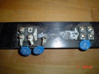
I use the setup as rectifiers for test PS's, these IXYS's do 200 amps, 600 amps peak, handle +500 watts each. ( NP stated he still makes a mess with thermal paste too)
Too much thermal past is just as bad as not using any at all. There is a correct amount for achieving best efficiency. Just like too much butter spread on a sandwich will give you a bad case of gas😱 .
Mark
Mark
Thanks again guys for your help today. This weekend I am doing a lot of DIY, but now taking a break. I had set aside the entire day for this but hit a snag which you all helped out with immediately while I did a little bbq for lunch.
This thread is great, but don't critize people and their thermal compound! Its just a messy test board (that happens to look a lot better than most of my finished products).
OK OK, its Jacco, nevermind. Don't see any pink standoffs in there, must have been his early work.
EDIT- and if Jacco popped out of my KSA 50 clone, I'd offer him a drink for his help (now at least a few times) saving me hours of effort. Hmmm..... "fat tire" (colorado) or "Pilsner Urquell" or .....something a little more sophisticated? I would also know where that weird rumbling noise inside the krell was coming from.....

heatsinking
After reading a lot of this thread im thinking of building my own ksa-50 clone.im very curious if a well-built clone will outperform my ksa-50(mk1)
im planning on using two 400va +/- 22Vac transformers, reason is i already got one so i just need to buy one (yes im dutch😉 )
i like the idea of not using fancooling because i really hate that fan in my krell, poor s/n ratio when listening to low volumes.
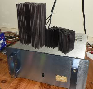
I've got some massive heatsinks but will these be enough to take it to a reasonable (mkII) bias-level wihout using a fan ?
here's a picture of them (this is for 1 channel-i have 2 sets)
Also, do i need to limit inrush-current with these transformers ?
Greetings,
Klaas
After reading a lot of this thread im thinking of building my own ksa-50 clone.im very curious if a well-built clone will outperform my ksa-50(mk1)
im planning on using two 400va +/- 22Vac transformers, reason is i already got one so i just need to buy one (yes im dutch😉 )
i like the idea of not using fancooling because i really hate that fan in my krell, poor s/n ratio when listening to low volumes.
I've got some massive heatsinks but will these be enough to take it to a reasonable (mkII) bias-level wihout using a fan ?
here's a picture of them (this is for 1 channel-i have 2 sets)
Also, do i need to limit inrush-current with these transformers ?
Greetings,
Klaas
jacco vermeulen said:Who needs a mother-in-law with you around.
Mr. Cleano, b4 I was just fooling with you, but now with a clean sink.....
 , thats not DIY...
😀
Upgrade to class-A 100W ????
Hi all Krell-clone builders
Im planing to build a KSA 50, but I would like to convert it for class-A 100W output power (at 8 ohms).
My questions are as follows:
What AC voltage (at mains transformer) should be enough for 100W outputs (38V?)
(output peak voltage must be at least 40V, 8 ohms)
What changes/upgrades/convertings must be made in the schematics to get a safe drive
and same data as the 50W clone?
Anybody tried to feed the driver board with a higher rails voltage then the output boards/devices
rails, for example 8-10 volt higher for to get a higher efficiency (power dissipation/power output?
I have tried to find information on this subject at the thread but have failed to find practical comments for this project, or am I wrong?
im planning on using two 400va +/- 22Vac transformers,
kvholio,
Being Dutch in this case isn't going to pay off😉 . Those trannys will leave you about 10 volts too low per rail but they would make a nice Aleph 30!. (22 X 1.35 = 29.7) volts DC. I generally use 1.35 as the multiplier to account for doide loss and so on. Some ise 1.4 as the multilplier but that generally doesn't hold true.
You need about a 56 vct 400VA transformer(29 X 1.35 = 39.15) per channel to make it to the +/- 37 volt give or take range on the stock KSA-50. This size tranny will work fine when biased for 50 watts class A.
Your KSA-50 shouldn't be all that noisy either.... is your fan ok? Perhaps going bad?
Mark
Flodstroem,
Stuart Easson has built one that I believe does 250 watts P ch. Your tranny assumption seems to be good for a KSA-100 as you will end up with about +/- 50 volt rails. The driver board can easily go to +/- 40 volts but I doubt that it'll go to +/- 50 volts without some minor changes. The zener limiting resistors would definately need to be re-calculated at the very least. Stuart designed a CSS for the front end that you might want to look into. I believe that it allows any level of rail voltage to be used up to +/- 100 volts.
There is a site here that has the early and later KSA-100 and KSA-80 schematics.
Also K-Amps has designed a nifty amp calculator that he might be able to send to you..... There is also the builders WIKI here .
Hope this helps and be sure to enter yours on the Krell-O-Tracker in the WIKI!!
Mark
Anybody tried to feed the driver board with a higher rails voltage then the output boards/devices
Stuart Easson has built one that I believe does 250 watts P ch. Your tranny assumption seems to be good for a KSA-100 as you will end up with about +/- 50 volt rails. The driver board can easily go to +/- 40 volts but I doubt that it'll go to +/- 50 volts without some minor changes. The zener limiting resistors would definately need to be re-calculated at the very least. Stuart designed a CSS for the front end that you might want to look into. I believe that it allows any level of rail voltage to be used up to +/- 100 volts.
I have tried to find information on this subject at the thread but have failed to find practical comments for this project, or am I wrong?
There is a site here that has the early and later KSA-100 and KSA-80 schematics.
Also K-Amps has designed a nifty amp calculator that he might be able to send to you..... There is also the builders WIKI here .
Hope this helps and be sure to enter yours on the Krell-O-Tracker in the WIKI!!
Mark
Flodstroem said:Anybody tried to feed the driver board with a higher rails voltage than the output boards/devices rails, for example 8-10 volt higher
I hope not, because that is not a wise thing to do.
Front end rails that are a few volts higher will compensate for voltage losses, more will only give trouble.
And even with 2 volt higher front rails the output stage will clip first, means you have to avoid clipping at all cost.
Mark, thanks for your reply
One of the reasons i asked about the +/-22 Vac transformer is that i dont think i need that much power, my loudspeakers have about 90 db/w sensitivity.
Also it will keep dissipation lower so maybe i can get away with not using a fan
-btw:my krell is not especially noisy, it's just "there".
Thats more than enough for me though
So maybe my question should be: will the amp work properly with this lower voltage ?
If not, no sweat, i'll just need 2 new ones
Greetings,
Klaas
Klaas,
Just be sure that the zeners in the front end are doing their thing at that lower rail voltage. An adjustment of the resistor in series with the zeners may be needed but otherwise it should work just fine. Probably about 30 wrms intop 8 ohms or there abouts.
Good luck on yours!!
Jacco,
I believe that he is talking about raising the rail voltage on the whole amp but his concern is for the main board. If he just uses Stuarts CSS on it instead of the zeners he should be fine and at alot higher power. Larger emitter resistors for the OP stage and higher wattage resistors for R-127 & 128 will probably be needed. Perhaps even going to beefier driver devices would be wise. One can use K-Amps calculatorhere to go fighre this all out.
Another course of action would be to build the KSA-100 MK-1 on the KSA-50 main and driver board. The 2 oz copper thickness of these boards is plenty for this. This should also be possible with some slight re-work of parts layout. Of course seomone will have to bribe me to sell them extra OP boards...... .
.
Mark
Just be sure that the zeners in the front end are doing their thing at that lower rail voltage. An adjustment of the resistor in series with the zeners may be needed but otherwise it should work just fine. Probably about 30 wrms intop 8 ohms or there abouts.
Good luck on yours!!
And even with 2 volt higher front rails the output stage will clip first, means you have to avoid clipping at all cost.
Jacco,
I believe that he is talking about raising the rail voltage on the whole amp but his concern is for the main board. If he just uses Stuarts CSS on it instead of the zeners he should be fine and at alot higher power. Larger emitter resistors for the OP stage and higher wattage resistors for R-127 & 128 will probably be needed. Perhaps even going to beefier driver devices would be wise. One can use K-Amps calculatorhere to go fighre this all out.
Another course of action would be to build the KSA-100 MK-1 on the KSA-50 main and driver board. The 2 oz copper thickness of these boards is plenty for this. This should also be possible with some slight re-work of parts layout. Of course seomone will have to bribe me to sell them extra OP boards......
.Mark
Thanks for the tips but............
Mark G. wrote:
Yes I have seen this threads earlier but it didnt contain any building projects for a 100W amp.
Yes Im aware of this (CCS) but regarding the design of the CCS by Mr Stuart E. I cant find a schematic anywhere in DIYAudio. Was this schematic ever posted? if yes, how to find it? If not...........is it possible for you Mr Stuart E. to post it here or PM a schematic for the purpose ?
BTW
GB of Power transformer: I have a post in the GB thread for a custom transformer. Now..... when things has been cleared out I will order customs transformer with the following data
prim. input 2x115V main voltage
sec. 1 and 2 output: 2x45V with taps for 2x38V (totals of ca 600VA for a mono block))
sec 3 1x12V for protection circuits)
(e.g. 38V for a KSA100, 45V for front end/driver board or suited for a mono block GB300D MOSFET amp).
If any interests look at GB site
Thank you all for your inputs
Mark G. wrote:
There is a site here that has the early and later KSA-100 and KSA-80 schematics.
Yes I have seen this threads earlier but it didnt contain any building projects for a 100W amp.
Stuart Easson has built one that I believe does 250 watts P ch. Your tranny assumption seems to be good for a KSA-100 as you will end up with about +/- 50 volt rails. The driver board can easily go to +/- 40 volts but I doubt that it'll go to +/- 50 volts without some minor changes. The zener limiting resistors would definately need to be re-calculated at the very least. Stuart designed a CSS for the front end that you might want to look into. I believe that it allows any level of rail voltage to be used up to +/- 100 volts.
Yes Im aware of this (CCS) but regarding the design of the CCS by Mr Stuart E. I cant find a schematic anywhere in DIYAudio. Was this schematic ever posted? if yes, how to find it? If not...........is it possible for you Mr Stuart E. to post it here or PM a schematic for the purpose ?
BTW
GB of Power transformer: I have a post in the GB thread for a custom transformer. Now..... when things has been cleared out I will order customs transformer with the following data
prim. input 2x115V main voltage
sec. 1 and 2 output: 2x45V with taps for 2x38V (totals of ca 600VA for a mono block))
sec 3 1x12V for protection circuits)
(e.g. 38V for a KSA100, 45V for front end/driver board or suited for a mono block GB300D MOSFET amp).
If any interests look at GB site
Thank you all for your inputs
Here are links to Stuarts CSS.....
Here is the first one.
The second post.
PCB for CSS.
More CSS
This one about higher power.
Could someone pleeze ad these posts links to the builders WIKI? Every time I go in there somhow I get things all messed up  .
.
Thanks!
Mark
Here is the first one.
The second post.
PCB for CSS.
More CSS
This one about higher power.
Could someone pleeze ad these posts links to the builders WIKI? Every time I go in there somhow I get things all messed up
.Thanks!
Mark
Thanks Mark:
Excellent Mark, Just what I needed. The project can continue.
Regards 😎
Here are links to Stuarts CSS.....
Here is the first one.
The second post.
PCB for CSS.
More CSS
Excellent Mark, Just what I needed. The project can continue.
Regards 😎
- Home
- Amplifiers
- Solid State
- Krell KSA 50 PCB