is the problem associated with both channels of the amp?? if so...it's likely to be just in the power supply section...
Yes, it's for both channel.
I suspected that the internal sophiscated protection circuit shut the amp down and that the main amplifier section is fine and that the problem is in the "start up board /regulator board/control board/front board" (as shown from the previous attached pictures). Now, the amp did not do anything when I press the power button.
For such a high power Class A amp, I'm surprised to see that there is only one fuse and that one fuse is NOT open. Does that give any clue? Noted that this one fuse is also located on the "front board".
Hi fcel,
This still may be a simple fault. It would make sense that the fuse is on the front panel. While I'm thinking of it, check the fuse holder clips for arcing. It would look pitted with black dots. Pushing the fuse in too hard tends to spead the clips apart.
Basically, have a look when you are up to it. If you start to feel uncomfortable taking the unit apart, stop and get help from someone more experienced.
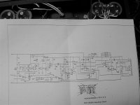
Looking at a KSA150 / 250 schematic, I see that they use K2 as the slow start relay, this shorts out those resistors you mentioned. There are a number of other switches and relays in the current path. The switches determine 115 - 230 V operation. K1 looks like the main AC contactor. F1 is 1A on this diagram and supplies the standby power for the protection and soft start circuits. Q1 is the regulator for this circuit, look for +11.4 ish volts on the emitter of Q1 or anode C11 / C12 or one side of R16.
Hope that helps. This schematic is on paper, so if you want it, I can email it to you. It's too big to attach.
-Chris
This still may be a simple fault. It would make sense that the fuse is on the front panel. While I'm thinking of it, check the fuse holder clips for arcing. It would look pitted with black dots. Pushing the fuse in too hard tends to spead the clips apart.
Basically, have a look when you are up to it. If you start to feel uncomfortable taking the unit apart, stop and get help from someone more experienced.
Looking at a KSA150 / 250 schematic, I see that they use K2 as the slow start relay, this shorts out those resistors you mentioned. There are a number of other switches and relays in the current path. The switches determine 115 - 230 V operation. K1 looks like the main AC contactor. F1 is 1A on this diagram and supplies the standby power for the protection and soft start circuits. Q1 is the regulator for this circuit, look for +11.4 ish volts on the emitter of Q1 or anode C11 / C12 or one side of R16.
Hope that helps. This schematic is on paper, so if you want it, I can email it to you. It's too big to attach.
-Chris
While I admire the advice and instruction given out on this topic I have a tendency to consider the liability on stuff like this before giving out instructions. I'm feeling like this guy is being taught to pack his parachute via a few posts for the first time before his first jump. Anyone directing him here could be held liable were he injured working on the amp . As for the straw... getting your head down in an amp with the potential for something burning up is ludicrous at best. Also, were he not to get the unit back together or back together correctly many shops will charge higher rates for what might have been a simple repair in the first place.
Mark
. As for the straw... getting your head down in an amp with the potential for something burning up is ludicrous at best. Also, were he not to get the unit back together or back together correctly many shops will charge higher rates for what might have been a simple repair in the first place.Mark
I actaully agree with Mark here,
this is a big amp with the potential to KILL, even though I know what im doing inside amps, most of the time, Id still feel anxious about putting my head close to the cicuit boards with a straw to my ear. If something were to blow up, well I wont mention why I woudnt want my head near it.
Id fully recommend getting someone else to fix it, be it an electrician or electrical engineer or whatever.
On another note it does sound like a relay or switch, I had this problem with an old switch, the switch worked in exactly the same way as you described. Push to to make contact, then it locks, you push it again and it breaks contact. Im my situation the amp would power up, the switch would crackle a bit then after some vibration therapy would stop. The amp would play for a while and then the switch would break (contacts not good) and the amp would stop. Now a relay is just a glorified switch so.....
But in the interest of your health dont do it yourself.
fcel
The problem as noted is related to the power supply or the protection circuit. More than likely their is a transistor or a caps that failing in the protection curcuit. If you feel you can fix it yourself you need to pull the amp a part and start measuring the components in the protection circuit. It very eary to determine if cap and transistors or bad even with out powering the unit up.
However if a transistor is shunted it will not measure and you will have to remove it. Of course you will need a good DMM and some skills in trouble shooting.
Also, If it was the power supply it should still make the sizzling sound when the amp start to play. My self, if it were mine I bite the bullet and send it to Krell. Then you know it will be fixed correctly.
Yea a switch that is possible, however with the kind of current that this monster pulls it would weld it closed or just burn it up. If you take you light switch and move the wiper to the middle you can here it making a sizzling sound. Of course the Krell pull much more current that a light.
Hi Mark,
I understand and agree with some of your points. I charge more more product disassembled or damaged for service. This is for the extra time & care the repair demands. I have had units written off by the owner/technical "friend". Oh well.
Having said this, I must recognise that we are adults, and will make our own decisions. I have also had units come in severly damaged by some of the respected service shops, and written off. What's better for the unit in question? At least the owner will tend to take due care given some instruction.
This seems to be a basic repair. It does give me the "willies" when non-technical people attempt amplifier channel repairs and bias adjustments. I think I draw the line there unless the individual shows that they have some understanding or are determined to do the work anyway. I'd rather point them the right way than have them slash about.
For others, the concern about the straw is unfounded if you use a normal long straw. Or a paper towel tube. I know it's not a high tech method, but it works in locating a noise. I don't stick my head into an amp either. I don't believe it's a cap vent or it would have gone "pop" already.
5th element, some of the worst damage I see is due to electricians and some engineers. Always take a repair to a competent tech who works on that type of gear. I'm not very good with TV's & VCRs. I know those techs aren't as good on audio amps as an audio tech.
-Chris
I completely agree. I wonder had he fixed it would he have just plugged it in to see if it works and so on....kapow! Anyway there are plastic stethoscopes that can be had for a few dollars from Chineese tool importers. They are alot safer to use than a straw.
Mark
Mark
highbias said:While I admire the advice and instruction given out on this topic I have a tendency to consider the liability on stuff like this before giving out instructions. I'm feeling like this guy is being taught to pack his parachute via a few posts for the first time before his first jump. Anyone directing him here could be held liable were he injured working on the amp
Mark
If I remember correctly, the member fcel built Aleph 2 (by himself, from scratch) http://www.passdiy.com/gallery/aleph2-p2.htm
so he should probably have enough "expertise" to fix a simple switch, if guided properly.
Mark, while I admire your sincere concern about his well being, your attitude is complete negation of diy spirit we try to share on this forum.
As for the straw, I think it is a genuine method and if it works, I might try it myself one day.
Personally, I would have never sent a unit for repair, if I didn't do my best at fixing the problem myself, first.
Peter,
You should know that a Krell amp like this is a much more sophisticated and complex than any Aleph or a simple GC. Also, he has no schematic. Having said that, it his $6000 amp not ours.
You should know that a Krell amp like this is a much more sophisticated and complex than any Aleph or a simple GC. Also, he has no schematic. Having said that, it his $6000 amp not ours.
But I doubt that the relay that kicks the mains to the big toriod is that much more complicated than any other relay.
I would follow the mains through the chassis until I found where they were inturupted if the big toroid and main caps are not charged. If they are, then looke for some protection circuit that is common to both channels.
I would follow the mains through the chassis until I found where they were inturupted if the big toroid and main caps are not charged. If they are, then looke for some protection circuit that is common to both channels.
It sounds just like a problem I had on my Rotel 990BX. It was on for an hour or so, then it would just pop a fuse. Antoher time it could be on for several days without any problems.
At last I found the problem, it was a diode in the inputstage for the constant current sources. The diode was all destroyed from it seems some left solderresin. The amplifier got unstable then.
This was just a tip, check for damaged diodes in the input stage 😉
At last I found the problem, it was a diode in the inputstage for the constant current sources. The diode was all destroyed from it seems some left solderresin. The amplifier got unstable then.
This was just a tip, check for damaged diodes in the input stage 😉
Hi Real_Macgyver,
That was the bonding "glue" used at assembly. When it turns dark, it gets conductive and eats the leads off components. I have repaired many items with that problem. It seems to need heat and moisture to do this.
-Chris
That was the bonding "glue" used at assembly. When it turns dark, it gets conductive and eats the leads off components. I have repaired many items with that problem. It seems to need heat and moisture to do this.
-Chris
Over the weekend, I did some troubleshooting and I was able to fix the problem. I would like to share this information with the members of this forum.
Troubleshooting sequence:
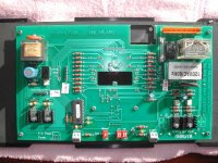
- From the attached “slow-start-board” picture, I did some troubleshooting. This is the board that is located behind the front face plate.
- I checked the diodes, resistors, capacitors and the transistors. They all checked fine.
- I also checked the rectifier board (picture not attached) that contains the 2 big rectifiers and the 4 small capacitors. They checked fine too.
- Then I go back and re-check the “slow start board” again.
- This time I did some visual inspection and I noticed that there are 2 cold solders on the 8 pins male connector - labeled as “J10” on the board (the 2 pins that has the black and white wires going to the rectifier board). "J10" is located on the upper right hand corner of the attached picture.
- This explains the “sizzling” sound at turn on, since there is a huge in-rush current during the turn on sequence.
- Sure enough, after I re-soldered the 2 pins and put everything back, the amp is fully functional again. I do not hear any more sizzling sound during the turn on sequence.
- I have also tested the amp by playing loud music for about 6 hours continuous and it did not shut down.
I believe the reason the 2 pins of the connector “J10” is developing a cold solder is due to the following:
- The black and white wire coming from the rectifier board is a hair too short.
- Over a period of many years, because of the constant wire pulling tension on the 2 most outer pins of the “J10” connector, it tends to “pull” the pins away from the solder joint once the amp is heated up and consequently caused the cold solder.
Troubleshooting sequence:
- From the attached “slow-start-board” picture, I did some troubleshooting. This is the board that is located behind the front face plate.
- I checked the diodes, resistors, capacitors and the transistors. They all checked fine.
- I also checked the rectifier board (picture not attached) that contains the 2 big rectifiers and the 4 small capacitors. They checked fine too.
- Then I go back and re-check the “slow start board” again.
- This time I did some visual inspection and I noticed that there are 2 cold solders on the 8 pins male connector - labeled as “J10” on the board (the 2 pins that has the black and white wires going to the rectifier board). "J10" is located on the upper right hand corner of the attached picture.
- This explains the “sizzling” sound at turn on, since there is a huge in-rush current during the turn on sequence.
- Sure enough, after I re-soldered the 2 pins and put everything back, the amp is fully functional again. I do not hear any more sizzling sound during the turn on sequence.
- I have also tested the amp by playing loud music for about 6 hours continuous and it did not shut down.
I believe the reason the 2 pins of the connector “J10” is developing a cold solder is due to the following:
- The black and white wire coming from the rectifier board is a hair too short.
- Over a period of many years, because of the constant wire pulling tension on the 2 most outer pins of the “J10” connector, it tends to “pull” the pins away from the solder joint once the amp is heated up and consequently caused the cold solder.
Attachments


- Home
- Amplifiers
- Solid State
- Krell KSA-300S will not turn on