TomWaits said:could put me back an easy $
The costs for building an amplifier used to amount 1/5th to 1/6th of the msrp, on average.
At the current exchange rate, the price of the KSA100MKII was $7,500.- here. (cheaper in Germany, more expensive in France. Tax differences.)
The costs for building a KSA100 would be $1,250-$1,500 at the 1986 price level, going by the leverage numbers.
jftr: In my low-cash student days i saved 6 months for parts, then took a $15 bus ride to Germany for 6 hours of shopping affordable parts. I bought my components wholesale, abroad, and at group discounts +20 years ago.
Costs go up in 20 years, transformers have become much, much more expensive.
Some passive/active components have become more expensive, some are cheaper nowadays.
Example: a common 1KVA toroid costs $216 in a shop here, 15 years ago the msrp was $156.
If prices of all parts would have gone up 40% as well, building the KSA100 would be in the +$2K league.
Think Canadian, hey, and it's heading towards CAD 2.5K. Time for a Moose beer.
Fortunately, output devices are so much cheaper nowadays and there's such a large trade in NOS capacitors and toroids. I've never built amplifiers as cheap as i do now.
A set of serial production power amp boards used to cost me well over $100.
And today, today there's Pierre Noël and Santa Mark who deliver amazing looking KSA100MKII Limited Edition boards at my doorstep for only $50, All-In !!!
The beauty of the KSA100MKII is that it is already a fully separated channel design, including the heatsinks.
Monaural designs usually have a 25% higher building cost, constructing the KSA100MKII in a stereo or monaural setup makes little difference in costs. Only a lot of time, if i calculated how much money i'd make during the hours i spend on ampies this would be a extremely silly hobby for me to be in.
MSRP of a 1500VA dual secondary toroid is well over $400 in this swamp. I bought a crate load of identical NOS 300VA's for a few dollars each once, but $40 for a 1.5KVA is an historical event.
36Vac secondaries, but maybe more sensible to save for another project instead of the KSA100MKII.
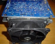
Coffins are a drag, fan heat ducts are cool.
OUTPUT1 & OUTPUT2
Hi,
the KSA100 mk2 power schematic shows the connections between the main board and the output board and the Zobel on the output including the two outputs (1&2).
The main and output schematics show the two connections "OUTPUT 1 + OUTPUT 2"
The main board PCB that we have has the two output connections in place at the corners.
Why is the 100mk2 wired this way?
What is gained by having the parallel links between the main and output PCBs?
Why two connections?
Why is the global feedback taken from the drivers rather than from the output?
How do we wire up the output stage to best use this arrangement of dual feedback?
OK, here are the answers as I gathered from rewiring an original Mk2:
The NPN and PNP boards were separated quite far from each other at the sides of the heat tunnel sinks. The way the Mk2 is wired is to keep the wires short to each section, as the board is about as wide as the tunnel. As you'll see the board's output connectors are 4 on top of each other at each side, so that the four wires leading to each output board can be tucked neatly together.
The global feedback cannot be taken from the outputs due to the mentioned separation. There's no real difference.
Unless you're using the same tunnels, the best way IMO is NOT as Krell has used do to symmetry issues. The board is laid out for separated NPN and PNP sections, so keep it that way.
I'd say use 1" standoffs for the boards and mount the devices (NPN left and PNP right) as close as possible or even perhaps partially underneath the boards. Make sure all 4 transistors have the same wire lengths.
For the speaker output Krell just took a random point, NPN on one channel and PNP at the other. This is IMO a very bad idea since the current from one rail now has to travel all the way to the board and from there to the other. Rather take a wire from each section to the speaker output or a similar innovative arrangement that is more symmetrical and would prevent the output stage current from returning to and through the board.
Hi P,
thanks for those clarifcations.
or
if only at the main PCB, that big trace from output 1 to output 2 on our Klone PCB would carry all the upper to lower current, but that prompts the question, where is the connection to the output relay?
If the Zobel is ONLY at the speaker terminals, does that mean the KSA100mk2 did not have the Zobel connected when the output relay was open?
thanks for those clarifcations.
you mean not the same as the output schematic?The NPN and PNP boards were separated
Are the emitter resistors of the upper NPN outputs connected to the Re of the lower PNP outputs? either at the heatsink or at the output relay?Krell just took a random point, NPN on one channel and PNP at the other
or
if only at the main PCB, that big trace from output 1 to output 2 on our Klone PCB would carry all the upper to lower current, but that prompts the question, where is the connection to the output relay?
why? What tolerance?Make sure all 4 transistors have the same wire lengths
which board? the main or output or relay?prevent the output stage current from returning to and through the board
If the Zobel is ONLY at the speaker terminals, does that mean the KSA100mk2 did not have the Zobel connected when the output relay was open?
The original used 4 output boards/channel. Each housed two transistors and their emitter resistors, and the boards were mounted on the four corner flanges of the heat tunnel; NPN's left and PNP's right.
The two boards on the same sides' emitter resistors and DC rails were connected to each other via a thick wire, and from there to the corresponding pads on the board along with the two base wires.
All of this is preceding the output relay board which is completely separate. What Krell did is to tap the speaker out (leading to the relay board and subsequently speaker conn & zobel) directly from one of the four boards' emitter resistor joint. That is, the other rail's rear transistors had to push current via the fronts, then the board, and then the fronts of the other rail before it reached the wire leading to the relay. Two wires would have been better to keep this distance shorter and more symmetrical and to prevent the current passing through the mainboard, but the rear transistors still has a longer path than the fronts. This is why a fully symmetrical mounting is preferred.
Substitutes for Q9-12 ?
Hello again!
Regarding substitutes for the pairs 2SA968/2SA2238.
Though I already bought substitutes before the parts list was created
and I have stock transistor of the Toshiba´s own substitutes they recommend, my question is if those are at least same or better substitutes than the suggested MJE15034/34 pairs?
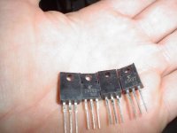
Toshiba recommended the the 2SA1837/2SC4793 complementary pair
(230V, 1A, 20W, hfe ≈100-320, FT 70-100 MHz) as a substitute for the OBS pair 2SA968/2SA2238. Also those transistor came in totally isolated To-220 cap (plastic) so you dont have to deal with isolator between device and heat transfer Aluminum plate. Any comments to this (maybe Jacco?).
Regarding those 1N5309, I missed the train, I wasnt online at those days you ordered. Any Current diodes left over, Im interested to buy 12 pcs (6 boards)? PM-me if there is somebody selling any?
Is there anybody going for the FETS ZVN/ZVP 2110G (SOT-223)? If there is I would like to participate for a group buy? Or am I to late in here to?
Regards 😎
Hello again!
Regarding substitutes for the pairs 2SA968/2SA2238.
Though I already bought substitutes before the parts list was created
and I have stock transistor of the Toshiba´s own substitutes they recommend, my question is if those are at least same or better substitutes than the suggested MJE15034/34 pairs?
Toshiba recommended the the 2SA1837/2SC4793 complementary pair
(230V, 1A, 20W, hfe ≈100-320, FT 70-100 MHz) as a substitute for the OBS pair 2SA968/2SA2238. Also those transistor came in totally isolated To-220 cap (plastic) so you dont have to deal with isolator between device and heat transfer Aluminum plate. Any comments to this (maybe Jacco?).
Regarding those 1N5309, I missed the train, I wasnt online at those days you ordered.
Any Current diodes left over, Im interested to buy 12 pcs (6 boards)? PM-me if there is somebody selling any?Is there anybody going for the FETS ZVN/ZVP 2110G (SOT-223)? If there is I would like to participate for a group buy? Or am I to late in here to?
Regards 😎
Nope, it will be the MJE for the drivers (but if its matter, 3 pair of drivers due to 6 pair of outputs)
Jacco, How do you think those behave as pre-drivers, do they fit right on place or how do you evaluate those drivers, good, ok, or bad ?
Jacco, How do you think those behave as pre-drivers, do they fit right on place or how do you evaluate those drivers, good, ok, or bad ?
Good, they only need a bias of a few mA to have an Ft of 30MHz and also have a favorable SOAR.
Nothing beats MJE devices when you are talking output current, but i think more of them as output devices, not drivers.
Btw : you can take a look see at the KSA100 schematic for the bias level of the pre-drivers, then take a peek at the pre-driver datasheet for the Ft value at that collector current.
Your point is good also, the drivers need not necessarily be limited to 2 per side.
Thanks Jacco, then it will be those in my KSA100mk-II Clone.
Regarding the other devices I lack, any suggestion for to where I can get my hands on a small quantity?
Regarding the other devices I lack, any suggestion for to where I can get my hands on a small quantity?
I suppose you'll have to wait till Mark returns from his bizz trip for the 1N5309.
You and me walky talky about the others, mail me.
Bullysheet P II: the pre-drivers will undoubtebly have twice as high Ft as the MJE drivers at the quiescent current levels they have.
Anyone who intends to use faster output devices better hit the gas for the mje drivers.
You and me walky talky about the others, mail me.
Bullysheet P II: the pre-drivers will undoubtebly have twice as high Ft as the MJE drivers at the quiescent current levels they have.
Anyone who intends to use faster output devices better hit the gas for the mje drivers.
Hi,
the predrivers, q9&10, dissipate about 850mW @ Iq=18mA. Medium power devices will benefit from a small heatsink (20C/W will suffice).
Q11&12 appear to pass about 17mA @ Vce=1.6V. This amounts to a dissipation of just 27mW.
Could a small signal device be used here?
Is there any disadvantage to not thermally linking q9 to q11 and q10 to q12?
Must q11&12 be medium power?
Must the fT of these pairs be matched (or a ratio) in any way?
Must the hFE of these pairs be matched (or a ratio) in any way?
I have only managed to find zvn2110g but not the zvp2110g.
I have ordered zvn/p2110a from Farnell.
I will have a 2pair set available for sale to a UK builder. Email if interested.
I have also ordered 3.5mA ccs diodes for the FET stage (from Rapid).
Does anyone see any problem with the extra 0.25mA through each FET and/or the 1k0 either side? I might change the resistors to either 820r or 910r to restore the voltage on the VAS Re. It depends on what tolerance the ccs diode turn out to have.
Flod,
I don't recall if you have told us what output devices you intend using nor the minimum load you are planning, but high gain plastic packaged BJTs take a lot of load off the drivers.
If you don't plan to use speakers that dip down to 2ohms then 2 pair of 20W drivers for a 6pair output stage should be adequate for most users. The old low gain 15003/4 do need a bit more grunt in the drivers and then 3pair of 20W devices or 2pair of MJE would become the reliable norm, particularly if you also plan less than 3ohms.
AndrewT said:
Flod,
I don't recall if you have told us what output devices you intend using nor the minimum load you are planning, but high gain plastic packaged BJTs take a lot of load off the drivers.
If you don't plan to use speakers that dip down to 2ohms then 2 pair of 20W drivers for a 6pair output stage should be adequate for most users. The old low gain 15003/4 do need a bit more grunt in the drivers and then 3pair of 20W devices or 2pair of MJE would become the reliable norm, particularly if you also plan less than 3ohms.
Planing to use 3 pair of MJE15032/33, and 6 pair of MJ15003/4 because I have plenty of heat sink in the mono blocks. Also, this amp will be a source to the type K2-S58/9800, (a friend of mine) having rather low impedance speaker (3-4 ohms?) But also, for experimenting with different types of speaker, eg. TL, ML-TQWT, Horns and that kind of weird stuff 😀 (low ohmic drivers, paralleling speaker etc).
😎
AndrewT said:re-calculate the dissipations in all the devices.
A few that particularly need attention are
r11&12
q9&10
q14 to 17
qoutputs
Will do.

Are you sure 44Vac gives only 60V? I would expect +-62Vdc (312W) when biased to 2.6A.
(44 x 1.414) - 1.4 = 60.81 volts. Load it down some and I may even have 58~59 volt rails.
Cheers,
Shawn.
jacco vermeulen said:The costs for building an amplifier...
Interesting comments but there were no metaphors in that post?
Everytime you(me, whoever) build an amplifier there is an opportunity to make it a little better which can further substantiate the investment. Your tone says,"go for it". And I say, "Why not? You only live once?" It's gonna hurt the wallet though.
I am certain I'll be using fans on the 100 and I'm pretty sure it will have to be a set of monoblocks.
Digikey came in today...very nice goodies.🙂
Shawn.
Flod,
I will see what I can do for you on the 1N5309 diodes. I did order some extras and if worse comes to worse I can just order you some more albiet at slightly higher 1-25 price but at least I can save you the horrendous shipping costs.
I thought that Toshiba might have a newer complimentary pair that they would reccomend. I will try to get ahold of some and see if there is any difference in sound.
More drivers/outputs is exactly what Krell did for the KMA-200 amp. I don't know how many KSA-200's they built but higher rails and more drivers/outputs.... this might be the next step with this amp. I've only seen one pair for sale over the years.... The KMA-200 was the size of the KSA-100!!
Mark
(Live in Forsyth, Montana!)
Thanks Mark. I´ll wait for your feedback, also I must inform you that I have some fishing lines out round the world. Will see if I can get some "Samples" for free. I´ll let you know next week.
The Toshiba´s mention here looks very promising.
Was there any GB for the 1/2W resistors ?
Regards😎
The Toshiba´s mention here looks very promising.
Was there any GB for the 1/2W resistors ?
Regards😎
No GB on the resistors. They are real easy to obtain. I'm still interested in the tranny GB and I'm wondering if AVEL would be willing to ship the GB lot of Krell trannys over here with a lot of their own stuff to make shiping more practical. They do have a stocked office here in the states on the east coast.
Mark
Mark
Yes I know they have an office in your country, but I dont remember if its only a trade office, or something more. I can speak to them and ask. There is no problem to ship internationally to GB members as long as place the order, and I pay the GB-order bill/invoice.
I have 4 pcs to order by now. Need 2 more for to get the 6 pcs price brake/discount.
Could post a GB thread in the Market Place forum (also I have a PayPal account).
Regarding secondaries: there is a winding, 64V x2 (128V ct) I think it was, Wandering if we should change this winding for to get an option for an extra voltage source (regulated) for the input and driver stage?
Must look at the KSA80 etc for to check specifications for this winding.
No matter what voltage, original, or our own specs for this winding = same price on x-former.
Regards.
- Home
- Amplifiers
- Solid State
- Krell KSA 100mkII Clone