Up to you. I prefer to design for modern, real-world audio sources, which will often output quite a bit more than 1.4 Vpk. My DAC will do about 6 Vpk or so. Unfortunately, the days of standard line-level voltages seem to be gone.
Ha ha now this 🙂 It is 2Vrms since 1982. Counts for the absolute majority of devices. Now one can of course continue creating one offs to couple with one offs (this is the most popular way) or ... have the rare source that disobeys orders adapted to 2Vrms (2 resistors in many cases). Accepting/buying/designing non standardized sources also is a choice.
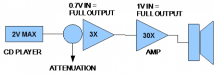
When CD started many amplifiers then had a separate CD input where the 2Vrms was attenuated to adapts to the volume levels of the then available low output level tuners, cassette players etc. In the audio magazines this was one of the decisive factors for selection 🙂 In the following decades this was solved and even digital tuners have 2Vrms outputs.
When CD started many amplifiers then had a separate CD input where the 2Vrms was attenuated to adapts to the volume levels of the then available low output level tuners, cassette players etc. In the audio magazines this was one of the decisive factors for selection 🙂 In the following decades this was solved and even digital tuners have 2Vrms outputs.
Last edited by a moderator:
By the way we can filament bias idht driver also, anybody tried this yet?
How did you think that?
Inboard of the IHT tubes the filament independent from the gain structure.
It is 2Vrms since 1982. Counts for the absolute majority of devices. ... and even digital tuners have 2Vrms outputs.
The target should not be 2Vrms though.
Now I am even more confused...
Assuming the goal is to go along with the standard voltage level, then why not design for the standard of 2 Vrms? Aiming for a an input sensitivity of 1 Vrms for full output just means that the standard 2 Vrms signal has to be attenuated by 6 dB in order to avoid clipping. This means you're throwing away 6 dB from signal-to-noise ratio. I don't see how/why that might be useful.
Can someone shine some light on this?
You are not alone who is confused. 😛
Suggesting too much sensitivity generates a designing problem in VAS stage selection.
Suggesting too much sensitivity generates a designing problem in VAS stage selection.
Suppose the current way of working with one offs.... Suppose a one off with 0.1Vrms input sensitivity and one with let's say 2.8Vrms input sensitivity. That means a standard 2Vrms source as a normal DAC/CD player/DAB+ tuner/streamer/media player will have different results on either one of the amplifiers. Now think of the position of the volume controller on either one. One will be overdriven at a very low position and the other one will have to be turned open way more.
in general most like comfortable volume at around 9 or 10 o'clock and at 12 o'clock things start to get pretty loud. Please don't underestimate the psychological aspect of this. Try it out and let a partner use an amplifier that needs to be at maximum output position for reasonable volume and then ask for an opinion....
OK, sources are most often 2 Vrms... Now you design the power amp to be 2Vrms input sensitivity. That means maximum output at maximum position of the volume controller. Therefor 1Vrms is more comfort considering the position of the volume controller as not many like to have the volume control at, for instance, 14 o'clock position for normal listening volume. As a volume control will alway be there (in this scenario preamps are completely unnecessary) to regulate volume I don't see a problem in attenuation as that will always be the case when one wants to regulate volume. Nothing is "thrown away" and the 2Vrms is a given with at least 95% of modern source devices. Secondly if you connect a very old source with way lower output like a phono preamp with 0.2Vrms output level you will have to turn volume to maximum to have reasonable volume. With 1Vrms input sensitivity one plays safe and creates a workable standard. With either the one off with 0.1Vrms or the 2.8Vrms input sensitivity one would have more issues...
600 Ohm is almost impossible with tube gear.....
Last edited:
It may be so but almost exclusively in the DIY tube world the issue of incompatible gear is most common either with impedances or with line levels. In fact in many of my experiments and demos it is most often that part where things don't work out. This while using standardized digital sources of all colors in nearly all cases.
The same sources that almost never pose problems with semiconductor amplifiers, class D stuff in all variations etc. So the issues are overcome in the semi world for decades. The often found stubbornness with regards to standardization is exactly what causes incompatibility. Why anyone would accept preamp X only to work with power amplifier Z is incomprehensible.
The same sources that almost never pose problems with semiconductor amplifiers, class D stuff in all variations etc. So the issues are overcome in the semi world for decades. The often found stubbornness with regards to standardization is exactly what causes incompatibility. Why anyone would accept preamp X only to work with power amplifier Z is incomprehensible.
Last edited:
Suppose the current way of working with one offs....
Nope. You advocated to go with "the standard", and that's why I explicitly aussumed "the standard" in my question.
I guess the whole confusion is related to "what are the design goals". Again, this really depends on what the user of the amplifier needs / wants. As you wrote: it's a choice to make! As long as this is DIY for single amplifier builds, I guess this choice should be up to the user of the amplifier.
in general most like comfortable volume at around 9 or 10 o'clock and at 12 o'clock things start to get pretty loud. Please don't underestimate the psychological aspect of this. Try it out and let a partner use an amplifier that needs to be at maximum output position for reasonable volume and then ask for an opinion....
Been there, done that. My folks either don't care or have very different opinions. Designing the gain of an amp based on the psychological implications from looking at the volume knob is not exactly my piece of cake. If the knob position really was an issue, I'd suggest to loosen that setscrew, turn the knob to the psychologically most accepted position, and tighten the setscrew again. 😉
As a volume control will alway be there (in this scenario preamps are completely unnecessary) to regulate volume I don't see a problem in attenuation as that will always be the case when one wants to regulate volume. Nothing is "thrown away"...
I suggest you read the "gain structure" article again (already quoted here a few posts earlier). The higher the amplifier gain is, the more attenuation is needed before the amp. Higher amp gain means that the noise at the amp input gets amplified more, reducing the signal-to-noise ratio of the system as a whole. That's why an attenuation from 2 Vrms to 1 Vrms before or at the amplifier input is equivalent to "throwing away" 6 dB of signal-to-noise ratio.

I suggest you read the "gain structure" article again (already quoted here a few posts earlier). The higher the amplifier gain is, the more attenuation is needed before the amp. Higher amp gain means that the noise at the amp input gets amplified more, reducing the signal-to-noise ratio of the system as a whole. That's why an attenuation from 2 Vrms to 1 Vrms before or at the amplifier input is equivalent to "throwing away" 6 dB of signal-to-noise ratio.
Have it your way. It is proven way of working elsewhere and of course it is also a trade off as nothing is perfect. Of course the shock is to design around and according predefined levels. Noise is not one of modern concerns with almost exclusively digital sources. In practice I often have to deal with oversensitive noisy/humming tube gear that is already overdriven with standard sources at low volume level thereby amplifying noise more than available semiconductor amplifiers as well so I must have a point somewhere 🙂
You could of course try it out once and see how it works in practice. I can tell from experience that stuff then will work together like it should be. The next discussion is then always about smaller caps sounding better than large caps (that come with defining a standard impedance level to lower noise levels).
Attachments
Last edited:
"Old Glory" schematic shown above was designed by Eric Barbour, and published in Glass Audio Magazine in 1995. His article was titled " Single Ended Glory for under $100. He assumed you had a very well stocked junkbox. Could not even get the tubes for that price today.
"Old Glory" schematic shown above was designed by Eric Barbour, and published in Glass Audio Magazine in 1995. His article was titled " Single Ended Glory for under $100. He assumed you had a very well stocked junkbox. Could not even get the tubes for that price today.
Maybe the Tubes were not included in the Build? -- And with inflation, $100 in 1995 is around $175 today.... Factor in boutique parts with Capacitors selling more than Double Barrel Shotguns and we have gotten used to the Ridiculous in Audio.
OK folks ... without further ado ... here is the Korneff 45!
I have been working with Jeff nailing this down over the last several months. I recently built it and it is one of the best tube amps I have ever heard! There is something to be said about simplicity and detail retrieval!
This is shared with Jeff's blessing too BTW ...
I had a pair of Monoblocks built that pretty much match the schematic that you posted.... B+ was lowered to 275 Volts, but otherwise it is pretty much identical. I have a question on the rectifier tube. The Builder said that I could use the 5U4G or 5Y3G or 5R4G among others... I don't need a lot of power out of this 45 amp, as I Bi-Amp and the 45 amp is only used on my 115db Horns. My question is what Rectifier Tube would be the easiest (Put the least stress) on other components on the Amp such as the Transformers, Tubes and Capacitors? I have tried the 5U4G and the 5Y3G Tubes and to my ears the 5Y3G sounded a bit better.
All comments will be appreciated. - Thanks!
- Home
- Amplifiers
- Tubes / Valves
- Korneff 45 Amp Circuit