
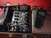
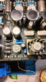
Yesterday afternoon I disassembled the card and I reworked the soldering, I put the jumpers back on the phono relays. The measurements I took from the AC transformer output areThis means the incoming DC voltage is 13.1V, and the transistor drops 1.28V. This is way too small. The incoming voltage should be higher (~15V) so the transistor drops ~2V, to have ~13V on the output. This also means the transistor is not operating correctly and cannot regulate the voltage.
Can you please try and measure the AC voltage on the transformer connections (where it says 12.8V), with all tubes ON ? I think we are coming close..
~8v on 6.3v output 13.1 on 12.6v output with all tubes on.
On the test point ~11.5 phono, ~11.8 line.
I am puzzled by the 8v power supply of the rectifier tube.
Attachments
Ok, now I try the new modifications, then at most I put the 25v 10000uf onesworth a shot to see if you could get closer to the target voltage.
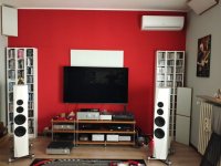
I'm listening......I'd say fantastic!!😅
No background noise, very natural sound, very good.
I thank heneser first of all for his great experience and professionalism, and above all for his patience with me.
Thanks also Derek and everyone who gave me advice.
We hope all goes well, good music to all.
No background noise, very natural sound, very good.
I thank heneser first of all for his great experience and professionalism, and above all for his patience with me.
Thanks also Derek and everyone who gave me advice.
We hope all goes well, good music to all.
Attachments


Erman, many thanks and I am happy you are enjoying your new amplifier! In the end it is worth all the effort....
Yesterday afternoon I disassembled the card and I reworked the soldering, I put the jumpers back on the phono relays. The measurements I took from the AC transformer output are
~8v on 6.3v output 13.1 on 12.6v output with all tubes on.
On the test point ~11.5 phono, ~11.8 line.
I am puzzled by the 8v power supply of the rectifier tube.
Hi hesener, thank you.
I wonder if the voltage can be improved to bring it to 12.6v.
These are the values I detected last week
.
I looked at the previous posts, and if I am not mistaken, the values you reported are:
Incoming AC: 13.3V
DC on the collector of the MJ3000: 13.1V
DC on the tubes (test pins): 11.8V
If that is correct, there is a huge voltage drop in the rectifier for the tube supply, which is odd. These diodes should be getting very very warm..... And it means, the transistor is not regulating anything and the hum removal is not really working.
Not sure if you can, but it would be interesting to change the rectifier diodes to SB550 (this is a 50V, 5A schottky rectifier diode which should fit). And, if possible, to measure the temperature of the rectifier diodes you have in there today, just to prove my point 😀
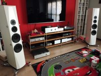
Nice speakers, by the way!
Incoming AC: 13.3V
DC on the collector of the MJ3000: 13.1V
DC on the tubes (test pins): 11.8V
If that is correct, there is a huge voltage drop in the rectifier for the tube supply, which is odd. These diodes should be getting very very warm..... And it means, the transistor is not regulating anything and the hum removal is not really working.
Not sure if you can, but it would be interesting to change the rectifier diodes to SB550 (this is a 50V, 5A schottky rectifier diode which should fit). And, if possible, to measure the temperature of the rectifier diodes you have in there today, just to prove my point 😀
Nice speakers, by the way!
Ok I will try to replace the diodes.
I built the speakers, they are the Ekta Grande project by Troels Gravesen, they sound very good 👍
Thank you
I built the speakers, they are the Ekta Grande project by Troels Gravesen, they sound very good 👍
Thank you

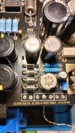
The diodes are hot, 73°C, the preamplifier has been working since this afternoon, no problems so far, it swine very well.II looked at the previous posts, and if I am not mistaken, the values you reported are:
Incoming AC: 13.3V
DC on the collector of the MJ3000: 13.1V
DC on the tubes (test pins): 11.8V
If that is correct, there is a huge voltage drop in the rectifier for the tube supply, which is odd. These diodes should be getting very very warm..... And it means, the transistor is not regulating anything and the hum removal is not really working.
Not sure if you can, but it would be interesting to change the rectifier diodes to SB550 (this is a 50V, 5A schottky rectifier diode which should fit). And, if possible, to measure the temperature of the rectifier diodes you have in there today, just to prove my point 😀
Nice speakers, by the way!
Attachments
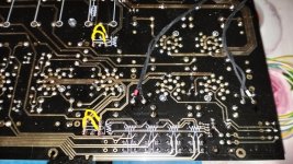
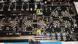
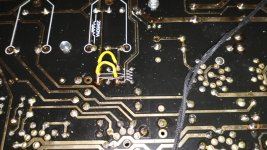
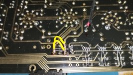
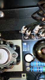
Are the points to be soldered of the relays in the photo all three PINs or just the ends?
I'm having a doubt about my modification suggested by heneser.
I did it like this.
Attachments

Congrats! So glad to hear that your unit is up and running flawlessly! And great choice of music! I just started on a second build for a friend. He's excited to get it running after hearing the one I had previously built.
Thank you, but I have to solve the problem of the 12.6v voltage.....
Sooner or later I will succeed 🙂
Sooner or later I will succeed 🙂
- Home
- Amplifiers
- Tubes / Valves
- Kondo KSL-M77 phono preamp clone project