Kofi wrote:
Answer to:
3a. Yes.
b. Think you've got it the other way round. 2 diodes =center tap grounded.( 4 diodes no ground, only use 0 to 300V or 600V.This is not relevant to your project.FYI only.)
c. Yes. It's actually quite simple,one goes on while the other goes off.(diode)
d. Yes.
e. Your socket is "bad". 😀
I think you are ready to go.
3. OK--- transformer wiring talk time:
a. So since I'm using the GZ34 full-waver, I must ground the center tap and use the far ends of the HT winding to feed the plates of the rectifier, right?
b. It sounds like the reason I don't use the center tap in the recitification process (other than referencing it to ground) is that I am using a two-diode full-wave rectifier rather than a four-diode job, right?
c. Based on Johan's response, it sounds like this will cause an effective 300V potential at each plate of the GZ34, which would be correct for this circuit; but I don't understand this:
quote:
The other winding end goes negative with respect to common and is not of concern, except for pushing up the peak inverse voltage that the rectifier(s) are required to handle.
... so, why does the other winding's negative potential not matter in the rectification process?
d. So, it seems like I could not use a transformer without a center tap for full-wave rectification with only two diodes. Is this right?
e. There's more than a little play in the GZ34 socket. I can almost blow it over when its mounted. I'll try and clamp the contacts shut.
Answer to:
3a. Yes.
b. Think you've got it the other way round. 2 diodes =center tap grounded.( 4 diodes no ground, only use 0 to 300V or 600V.This is not relevant to your project.FYI only.)
c. Yes. It's actually quite simple,one goes on while the other goes off.(diode)
d. Yes.
e. Your socket is "bad". 😀
I think you are ready to go.
Kofi Annan said:c. Based on Johan's response, it sounds like this will cause an effective 300V potential at each plate of the GZ34, which would be correct for this circuit; but I don't understand this:
... so, why does the other winding's negative potential not matter in the rectification process? Kofi
Because the diode only allows current to flow in one direction. The transformer swings both ways. When the voltage swings positive behind the rectifier, current flows. When it swings negative, current stops on that leg of the rectifier. It's called full wave, because one side or the other is positive at any given time, except for a small instant at the changeover point.
Might be easier to draw up the rectifier and transformer and imagine current flow. For simplicity sake, use diode icons in the diagram. Current flows only in the direction of the diode "point". Think of current flowing in one direction in the secondary, then the other. For each case, follow the flow from positive to ground and even write down the voltages at various points in the circuit. Once you've done that have a clear picture, you can read the next paragraph.
Ok, now to throw in a curve: Current flow in a circuit is by convention from "positive" to "negative". But when the convention was decided (guessed), it wasn't known how electrons were actually moving. So the chances were 50:50 of getting it right. Oops, they got it wrong. Electrons actually flow from negative (they are negative after all) to positive. So in your tube, the cathode generates a cloud of electrons. Since the plate is cold and can not generate an electron cloud electrons can only flow from the cathode to the plate. Or, by convention - remember that goof up, current can only flow from plate to cathode.
Sheldon
Kofi,
Others have responded to your #179. Perhaps further, and apologies if I was vague:
One references to common or in this case the centre tap (as in the popular notation 300 - 0 - 300). Thus the two ends of this complete winding are always out of phase. At the exact time when one end is at +330V, the other is at -300V (with respect to common), whence the total of 600V across the ends. The positive side always charges the filter capacitor (and feeds the equipment) by virue of a diode only conducting in one direction. This conduction would alternate between the two ends (diodes). The other end is during its respective negative half cycle (i.e. 100/120 times/second) not of concern because that end's diode is in cut-off. But when selecting diodes one needs to select for the maximum inverse voltage (i.e. that which it can stand in the cut-off state without breaking through). If you look at things in the centre-tapped version of a full-wave circuit, that maximum voltage across the non-conducting diode will be the peak value of the +300V side (424V), plus the peak value of the negative end, which is another 424V, i.e. 848V in total between the cathode of the non-conducting diode and its anode. Tubes do not have too much of a problem here but with silicon diodes this peak inverse voltage (PIV) will need to be at least 1 KV (one does not work on the margin).
If you look at what is called a bridge rectifier fed by only one winding, two diodes will always conduct at any instant. One will "short" the positive side to the +330V (actually +424V), while the opposite one will "short" that end of the winding to common. During the next half cycle the condition will simply reverse. (If you simulate this by holding your thumb and index finger of one hand apart and consider those to be the winding ends, then, if you rotate your hand back and forward through 180 degrees round the axis of the fore-arm, it will graphically represent the winding polarity. In this case the PIV of each diode needs to be only half that of the previous condition. The whole transformer winding will be delivering current every half cycle instead of every alternate one as before, but you will need only one 300V winding, not two (halves). In that respect the full-wave bridge rectifier scheme is to be preferred to the previous one - better efficiency, lower rectifier PIV voltage, etc. (It is of course more suited to semiconductor diodes, where each is separate.)
Kofi, this description may have been overly simplistic; you might have grasped much of this earlier. Once you grasp it it is very simple (as is much of audio electronics!).
Good luck with your project.
YEAH! THANKS!
Short response now-- longer response later (I'm at the UN and we've got a lot going on today).
So, if I understand correctly about the center tap, it needs to be grounded so that the negative voltage on the non-conducting diode has a ground reference and can be shorted there. By shorting the continually-changing negative side, we are effectively valuing that side at zero volts.
Furthermore, since this is valued at zero volts, the positive side (+300 at peak) will be compared against that zero and only provide +300 volts to the first filter capacitor instead of the +600 volts it would hhave provided if the center tap was left floating and referenced essentially at -300V.
Can I get partial credit if some of this is right?
Kofi
Kofi,
Yeah - the UN businesses are enough to get anybody down.
You can get partial credit, but we need to try again.
Let us forget about the negative voltage side and in fact a centre tap at all. Let us start with one winding, earthed at one side, and because the voltage is AC (this is electronics for you - how can a voltage be alternating current - no wonder one gets confused) - because of the AC the other end of the winding will be alternately +300V and -300V respective to common when displayed on an oscilloscope, 60 times a second (I will refer to 60 Hz only). If you agree with that, then you can connect a diode to the free end such that it conducts when that end is positive with respect to common, and thus feed a load resistor with the peak of that +300V. But every alternate half-cycle there will be no voltage across the load resistor, because during those times that winding end is negative referred to common, thus the diode will not conduct. This is called half-wave rectification for obvious reasons.
When you are satisfied with this, we can take another (separate) 300V winding with the same state of affairs as above (it could in fact be two transformers). Now, if you arrange the phase of that second winding (transformer) such that it is out of phase with the first one, you will have the situation where each diode will still conduct only every other half-cycle, but one will be on exactly when the other is off. Should you connect two separate beams of a dual-beam oscilloscope each to a diode, you will see a positive half-wave every half cycle, from alternate scope beams when they are positioned to co-incide at 0V.
The rest is a small step. Since one side of each separate 300V winding is connected to common, they are in fact connected together. Drawing this out, you should now see that the two windings together in fact forms a centre-tapped 600V winding, or 300-0-300V as commonly designated. (They can of course be on the same transformer in the end.)
After this exercise I am sure the rest will fall into place - but do ask again.
Regards
Thanks for being patient!
Sounds like we do.
I think I understand this. I really do!
Got it. So it looks like this:
/\/\/\/\/\/\/\/\/\/ (full wave)
Instead of this:
/\__/\__/\__/\__ (Half wave)
OK-- se here's where I fall down just a bit. My real question is-- why do you need a center-tapped transformer for full-wave rectification with two diodes? Actually, my real question is-- when do I need to stop using the salve? But since you're likely not in the endocrinology field, the first question will do nicely.
It sounds like the reason the center tap is required is to preserve the out-of-phase conditions of the windings, but I'm not sure.
Sorry to try your patience. Mrs. Annan will gladly knit the appendage accoutrement of your choice should you care to answer.
Also. I checked the socket for the GZ34 and its fine. When I rock the tube in the socket, the pins rock with it. And I like to rock.
ROCK!
KOFI!
You can get partial credit, but we need to try again.
Sounds like we do.
Let us forget about the negative voltage side and in fact a centre tap at all. Let us start with one winding, earthed at one side, and because the voltage is AC (this is electronics for you - how can a voltage be alternating current - no wonder one gets confused) - because of the AC the other end of the winding will be alternately +300V and -300V respective to common when displayed on an oscilloscope, 60 times a second (I will refer to 60 Hz only). If you agree with that, then you can connect a diode to the free end such that it conducts when that end is positive with respect to common, and thus feed a load resistor with the peak of that +300V. But every alternate half-cycle there will be no voltage across the load resistor, because during those times that winding end is negative referred to common, thus the diode will not conduct. This is called half-wave rectification for obvious reasons.
I think I understand this. I really do!
When you are satisfied with this, we can take another (separate) 300V winding with the same state of affairs as above (it could in fact be two transformers). Now, if you arrange the phase of that second winding (transformer) such that it is out of phase with the first one, you will have the situation where each diode will still conduct only every other half-cycle, but one will be on exactly when the other is off. Should you connect two separate beams of a dual-beam oscilloscope each to a diode, you will see a positive half-wave every half cycle, from alternate scope beams when they are positioned to co-incide at 0V.
Got it. So it looks like this:
/\/\/\/\/\/\/\/\/\/ (full wave)
Instead of this:
/\__/\__/\__/\__ (Half wave)
The rest is a small step. Since one side of each separate 300V winding is connected to common, they are in fact connected together. Drawing this out, you should now see that the two windings together in fact forms a centre-tapped 600V winding, or 300-0-300V as commonly designated. (They can of course be on the same transformer in the end.)
OK-- se here's where I fall down just a bit. My real question is-- why do you need a center-tapped transformer for full-wave rectification with two diodes? Actually, my real question is-- when do I need to stop using the salve? But since you're likely not in the endocrinology field, the first question will do nicely.
It sounds like the reason the center tap is required is to preserve the out-of-phase conditions of the windings, but I'm not sure.
Sorry to try your patience. Mrs. Annan will gladly knit the appendage accoutrement of your choice should you care to answer.
Also. I checked the socket for the GZ34 and its fine. When I rock the tube in the socket, the pins rock with it. And I like to rock.
ROCK!
KOFI!
Kofi Annan said:
OK-- se here's where I fall down just a bit. My real question is-- why do you need a center-tapped transformer for full-wave rectification with two diodes? Actually, my real question is-- when do I need to stop using the salve? But since you're likely not in the endocrinology field, the first question will do nicely.
It sounds like the reason the center tap is required is to preserve the out-of-phase conditions of the windings, but I'm not sure.
Sorry to try your patience. Mrs. Annan will gladly knit the appendage accoutrement of your choice should you care to answer.
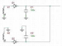
Let's see if this helps:
you will be using two half-wave power supplies in parallell, but with each of the diodes conducting one half cycle each. So you to get this you put two windings in opposite phase (when one goes to +, the other goes to - referred to earth), tied by its ends.
In the drawing, when D1 conducts, D2 doesn't, and too, when D2 conducts, D1 doesn't.
Now we just tie both earthed ends of the windings and we get the good old center tapped transformer.
HTH
Gaston
Attachments
Had some time to absorb this concept and now I get it. I really do.
I pretty much had the rectification concept OK, but the center tap issue was throwing me for a loop.
Rest assured. Kofi's got it.
Now-- I'm going to start wiring this weekend, so I'm kinda curious as to the best method here. I have some nice wire from Radio Daze that I though looked cool and shouid be able to handle the voltage. Unfortunately, they sent me stranded instead of solid. I thought about ordering some more, but I think I'll just work with the stranded stuff.
Based on my review of Morgan Jones' Building Valve Amplifiers, I think I should wire the heaters first, see if they glow, then go to the next step. I thought about wiring the heaters with some 22AWG solid core Belden wire since it would be easy to twist, but I wonder if the gauge would not be appropriate for the heaters.
Also, once the heaters are wound, what's the next logical step for the wiring?
Another one: the EL84 output tubes are to be wired for ultralinear operation. According to the schematic, it looks like g3 is shorted to the cathode, but I can't be sure. Also, it looks like the input is to g1 and the output to the transformer is from g2 but again, not sure...
I know. Too many questions. I promise I'll try not to be a dumbass this time when you respond.
Kofi
Kofi,
I wire stuff for use in aircraft and so use VERY conservative ratings. The maximum continuous currents (DC Amps or AC RMS Amps) vs common wire gauge ratings I use for aircraft stuff are below. As tube amps are a HOT environment I simply use these same conservative ratings for tube amp hobby work:
12 AWG - 16 Amps
16 AWG - 8 Amps
18 AWG - 5.7 Amps
20 AWG - 4 Amps
22 AWG - 2.8 Amps
24 AWG - 2 Amps
26 AWG - 1.4 Amps
28 AWG - 1 Amp
30 AWG - 0.7 Amps
These are the ratings for maximum ambient temperature of 70 degrees C and when you bundle up to 6 wires in a single loom.
If you bundle more than 6 wires together, then these current values need to be further multiplied by 0.85
With your 22 AWG and just 2 wires twisted together your are probably OK to about 3.5 Amps. If total heater current exceeds that, then run multiple heater twisted pairs back to the transformer instead of daisy chaining . In anycase I would run separate twisted pairs for the two channels and just join them at a tag strip or terminal block back near the transformer. This also gives you a convenient place to add balancing resistors to ground (if the heater winding does'nt have a centre tap) or to connect that heater cetre point to say 20 or 30 Volts DC if hum is a problem.
Push heater wires into then corners of the chassis and route them away from the inputs and the input tube.
Finally DO NOT twist the heater wires too tightly, 3 twists per inch is quite adequate.
Cheers,
Ian
Kofi Annan said:Also, once the heaters are wound, what's the next logical step for the wiring?
Another one: the EL84 output tubes are to be wired for ultralinear operation. According to the schematic, it looks like g3 is shorted to the cathode, but I can't be sure. Also, it looks like the input is to g1 and the output to the transformer is from g2 but again, not sure...
I know. Too many questions. I promise I'll try not to be a dumbass this time when you respond.
Kofi
Kofi,
IMO, if you didn't yet, you have to decide which kind of ground strategy you will follow, and, well, follow it.
I mean, are you going to use a ground buss, star topology, a mixture, some esoteric grounding topology ?
In pentodes, most of the times, g3 (the supressor grid) is internally connected to cathode. When the connection is available in the base of the tube, it should be connected to cathode too, unless you have something *very* specific in mind.
In UL PP, each g2 (the screen grid) is connected to the OPT tap corresponding to the anode of the same tube. For some tubes, it is necessary to connect a resistor between g2 and the OPT tap.
You can also connect g2 to anode through the resistor and the tube will then operate in "triode mode".
g1 (the signal grid) is, as you say, the input of the output stage.
So resuming, you should have:
Anode - connected to OPT end.
g3 - internally connected to cathode.
g2 - connected to OPT tap, either through a resistor or a plain cable.
g1 - input
cathode - connected through parallelled RC to ground.
There are never too many questions when they come from the UN SG...
Gaston
Great! Thanks!
So the pair of EL84s and the E88CC will consume about 1.7A. I'll definitely need to run two separate pairs for each channel and one pair at 20AWG for the GZ 34 rectifier which pulls about 1.9A, according to the datasheet.
Perfect. Its all coming together.
Now about the wiring for the EL84s, according to the datasheet, g3 and the cathode appear to be internally connected, right? So that means that g1 gets the input signal and the output for push-pull ultralinear is taken from g2.
The even dumber question:
If the cathode and g3 are riding together due to an internal connection, why is this not a tetrode?
State education, fellas.
Kofi
Kofi Annan said:If the cathode and g3 are riding together due to an internal connection, why is this not a tetrode?Kofi
There are still 5 electrodes, hence pentode. The fact that two of the grids have the same voltage reference doesn't mean that they don't have independent functions. In this case, G3 gathers up stray electrons bounced off the plate - different function from the cathode, which generates electrons to send to the plate.
In fact a triode connected pentode is just that. It's not exactly a triode. It's a lot like a triode in that G2 essentially becomes part of the plate. In this case, G2 and the plate do have the same function, but it's going to behave a little different from a tube with only a plate. That extra "plate" is in a different position and has a physically different structure.
Sheldon
Kofi,
All I can add is the saying:
He who asks is a fool for five minutes. He who does not ask is a fool for the rest of his life.
We all came the way of asking the most basic questions at some time. Even when you read a textbook, you get answers - ergo, there must have been questions. Who denies this, is either a liar or a self-serving arrogant idiot.
Regards.
Kofi Annan said:
If the cathode and g3 are riding together due to an internal connection, why is this not a tetrode?
State education, fellas.
Kofi
The fact is that the EL84 is a true power pentode. There is a kind of power tube, sometimes referred to as pentode that actually *is* a tetrode. The correct name (an it was patented that way) is "beam power tetrode" or "beam power tube". Previously, it was called a "kinkless tetrode" due to the form of its anode characteristic curves, and they operate on a different principle than that of the true pentodes. AFAIK, the "true" power pentode was the industry answer to the (patented) beam power tube.
The catode and g1 are exactly the same as in a power pentode, the screen (g2) is made in such a way that the wires are in the shadow of the g1. g3 is called "beam forming electrodes", and direct all of the electron flux to the plate.
Having g2 in the shadow of g1 and ideally out of the electron flux raises the efficiency and lowers the g2 current.
The 6L6 family is a good example of beam power tubes, while the EL34 is the same for "true" power pentode.
AFAIK, the "true" power pentode was the industry answer to RCA's (patented) beam power tube.
Gaston
Actually, I read just the other day that it was the other way around, that the 'kinkless tetrode' AKA beam power tube, was developed to avoid infringements of power pentode patents held by Philips.
Actually I also have it as Ilimzn. I recall that the EL34 was a follow-up of the EL37, which was there before the 6L6 clan - but not to put a fine point on that now. If of interest I have the history at home (where I am not now) and can clear up later.
Following Kofi's example of asking, I have a puzzle. Firstly, I think there is confusion with some because the beam power tube actually has two advantages, the main one being not the beam configuration, but the aligned grids with the effect that Ghpicard described. But I read that there is a beam EL34, and I am looking for an exact description. Distributors here have not heard of it. It would appear that this EL34 has beam confining plates attached to G3 as in the 6L6 etc. That would have some advantage in keeping electrons away from too wide a sweep, but as far as I am able to judge from pictures (not very clear) it is not an EL34 with aligned grids. If so, it is still a classic pentode, not to be compared with the classic beam tube. Does anybody have any information on this? Someone else has mentioned this on another thread where I will also enquire, but since the subject came up here ........
Regards.
Johan Potgieter said:But I read that there is a beam EL34, and I am looking for an exact description...
Maybe this has to do with the KT77 which is sometimes referred to as a beam tetrode, and as an equivalent to the EL34?
Johan Potgieter said:But I read that there is a beam EL34, and I am looking for an exact description. Distributors here have not heard of it. It would appear that this EL34 has beam confining plates attached to G3 as in the 6L6 etc. That would have some advantage in keeping electrons away from too wide a sweep, but as far as I am able to judge from pictures (not very clear) it is not an EL34 with aligned grids. If so, it is still a classic pentode, not to be compared with the classic beam tube. Does anybody have any information on this? Someone else has mentioned this on another thread where I will also enquire, but since the subject came up here ........
Regards.
Don't know about EL34s, however, the 6BQ5 has been made both ways: conventional pentode and as a beam tube (probably not the only type so made). So long as it matches the described characteristics for the type, how the manufacturer decides to meet the design criteria is up to them. What that does to the sonics, who knows?
Johan Potgieter said:Actually I also have it as Ilimzn. I recall that the EL34 was a follow-up of the EL37, which was there before the 6L6 clan - but not to put a fine point on that now. If of interest I have the history at home (where I am not now) and can clear up later.
I will open a new thread just not to hijack Kofi's one.
All of us know what happens at UN when somebody hijacks things...
Gastón
Peacekeeping forces in Buenos Aires. That's what.
Don't. Mess. With. Me.
PS-- I'll start wiring tomorrow AM. You guys need to be up by about 9:30 EDT (US) to answer questions. I'll need pager information for at least one of you should the website go down and you can visit my live solder slinging at www.koficam.com.
Adios.
Kofi
Don't. Mess. With. Me.
PS-- I'll start wiring tomorrow AM. You guys need to be up by about 9:30 EDT (US) to answer questions. I'll need pager information for at least one of you should the website go down and you can visit my live solder slinging at www.koficam.com.
Adios.
Kofi
- Status
- Not open for further replies.
- Home
- Amplifiers
- Tubes / Valves
- Kofi Annan in: "Push and Pull with Me"