I wouldn't worry about the input tubes picking up anything from the rectifier. If your layout is anything like the second one, you should have plenty of space between components. The main power transformer will be your biggest source of leakage inductance. Everything else is much less.
Sheldon
Sheldon
Kofi, no ...
But (under certain conditions perhaps a wreckless statement to make) hum and induction do not come all that easy. Your present suggested layout look to me quite in order. As you say, you might be worried about the output going to the right-hand side, but then do not be scared to take leads the long way round (lengths on under-chassis scale mostly make no difference. Don't be alarmed by such advice often given, that would make a difference only in r.f. It is far more important WHERE you route stuff.) In this case, you may route both loudspeaker leads in the chassis corners; from the left to the side nearest to you (per photograph), then from left to right, then up the right hand side to wherever you want to exit.
I want to make another comment regarding transformer placement. I must confess to also be a little naughty regarding making things very small (was it Sheldon who admitted to similar temptations?) See what Quad II did! But lately I mounted all 3 transformers next to each other in all of a 2 x 100W amplifier, and without the "90-degree" alignment! Slight advantage was that the transformers were C-core (stray field thus a little more contained), but I feared the worst. When testing with the (huge) power transformer on and measuring on the outputs without tubes in, there was a bit of hum. But point is that with the output tubes in, it just about disappeared. One must remember that induction into a loaded output transformer is significantly lower than into an open one. Now I do not imply to just go and be wreckless, but the matter should be kept in consideration.
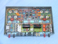
I am further going to be bold and try to post an under-chassis view of the above amplifier (weight about 23 kg - 52 lb). Now please, this is NOT supposed to be a general example of anything other than perhaps a little wrecklessness, but it shows what can work. [The tube (actual amplifier) part is on the far side - the near side contains power and safety circuitry.] It will be in a following post for possible file size problems.
Regards
But (under certain conditions perhaps a wreckless statement to make) hum and induction do not come all that easy. Your present suggested layout look to me quite in order. As you say, you might be worried about the output going to the right-hand side, but then do not be scared to take leads the long way round (lengths on under-chassis scale mostly make no difference. Don't be alarmed by such advice often given, that would make a difference only in r.f. It is far more important WHERE you route stuff.) In this case, you may route both loudspeaker leads in the chassis corners; from the left to the side nearest to you (per photograph), then from left to right, then up the right hand side to wherever you want to exit.
I want to make another comment regarding transformer placement. I must confess to also be a little naughty regarding making things very small (was it Sheldon who admitted to similar temptations?) See what Quad II did! But lately I mounted all 3 transformers next to each other in all of a 2 x 100W amplifier, and without the "90-degree" alignment! Slight advantage was that the transformers were C-core (stray field thus a little more contained), but I feared the worst. When testing with the (huge) power transformer on and measuring on the outputs without tubes in, there was a bit of hum. But point is that with the output tubes in, it just about disappeared. One must remember that induction into a loaded output transformer is significantly lower than into an open one. Now I do not imply to just go and be wreckless, but the matter should be kept in consideration.
I am further going to be bold and try to post an under-chassis view of the above amplifier (weight about 23 kg - 52 lb). Now please, this is NOT supposed to be a general example of anything other than perhaps a little wrecklessness, but it shows what can work. [The tube (actual amplifier) part is on the far side - the near side contains power and safety circuitry.] It will be in a following post for possible file size problems.
Regards
OK, here goes. The transformers are at the bottom, terminals being on the 3 x 2 pale blue terminal strips.
Well Kofi, Johan has set the bar high there. If you can make your project look like that, the rest of us are going to be asking you for tips.
Sheldon
Sheldon
Ain't never gonna get it lookin' that good. Nice job, Johan!
Finished the drilling today-- not the greatest, but better than anything I've built before. Its got three coats of clear laquer. That was the easiest to do, so I did that. Story of my life.
I'll start wiring this week if I get the chance, but more likely next weekend.
One question-- the rectifier tube is really loose in its socket. I used an eight-pin octal for the GZ34. I don't know if the looseness will be a problem, but I bet one of you guys will have something to say about it, huh?
Kofi
Attachments
EC8010 said:Your present arrangement of mains transformer and output transformers is fine provided that you ensure that the output transformers have their centres on the centre line of the mains transformer,
any reason for this? possibly aesthetics?
thank you.
I think that the 90 degree coupling with the power transformer minimizes the possibility of flux leakage from the power transformer being picked up as hum by the OPT. If the cores of the transformers are lined up directly but 90 degrees offset, the flux leakage impact is at a minimum.
I think. Is that right?
So, any ideas about my loose GZ34 socket?
Also, I have another DumbKofi question:
My power transformer is the 272JX from Hammond, and its a 300-0-300 job. Anyway, Morgan Jones' schematic for the Bevois Valley shows that he has a center-tapped transformer with each end of the HT supply going to the GZ34 plates and a grounded center tap.
Here it comes. The dumness, I mean:
Now, is there really 300 volts between the two ends of the secondary? Or is there 600 volts between those leads, but only 300 volts between them with a grounded center tap?
You're shaking your head. I know it.
Kofi
You are right.600V AC. end to end.300V to center tap.
edit- Same goes for the 90 degree offset.
If the socket (GZ34) is loose try using tiny jeweler's screw driver or similar stiff pin to push/squeeze spring metal contact closer.
If it's the GZ4 (tube) the glass envelope has a seal effect with the 8 pins independant of the base like those 9 pin small signal tubes,the vacuum should be in tact,still I'm not sure about this.
You are right.600V AC. end to end.300V to center tap.
try using tiny jeweler's screw driver or similar stiff pin to push/squeeze spring metal contact closer
Good idea. Thanks!
Thanks! So, does that mean that if I ground the center tap I'll have 300V between the two ends of the secondary? How does that work?
Kofi
Kofi Annan said:
So, does that mean that if I ground the center tap I'll have 300V between the two ends of the secondary? How does that work?
Kofi
if measured from end to end, you'll get 600V.
Kofi Annan said:Now, is there really 300 volts between the two ends of the secondary? Or is there 600 volts between those leads, but only 300 volts between them with a grounded center tap?
The same transformer would be specified in the UK as a 300V-0-300V transformer and in the US as a 600V CT transformer.
The business with the centre lines and 90 degrees is not aesthetics, it's to minimise hum.
to kofi
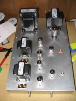
can you tell me which iron is which in the photo?
I assume the 2 at the front are the output. but somewhat confused with those at the back.
thank you.
can you tell me which iron is which in the photo?
I assume the 2 at the front are the output. but somewhat confused with those at the back.
thank you.
i'm not kofi but those two at the back is the power transformer (left) and choke (right). of course kofi can shoot me if i'm wrong 😀
now kofi, i just hope hammond fixed the over heating problem of the 270 series. it would have been better if you got the 370 series.
now kofi, i just hope hammond fixed the over heating problem of the 270 series. it would have been better if you got the 370 series.
arnoldc said:i'm not kofi but those two at the back is the power transformer (left) and choke (right). of course kofi can shoot me if i'm wrong 😀
now kofi, i just hope hammond fixed the over heating problem of the 270 series. it would have been better if you got the 370 series.
well I do know it's a power transformer and choke at the back. 🙂
but what I want to know is which is which. I can't read the labels. 🙂
Thanks! So, does that mean that if I ground the center tap I'll have 300V between the two ends of the secondary? How does that work?
Kofi
Mr.Annan,
No,you will have what is said before.Look at your schematic,in your case you are using 2 diodes (GZ34) so you need to ground the center tap for the ac to dc rectification to work for full wave conversion.But if 4 diodes (bridge) the center tap is not used and the you would only need a 0 to 300V transformer.So there are 2 methods of conversion,2 and 4 diodes.
For tubes 2 pcs. of GZ34 would add to costs.Same for solid state,in this case extra winding for transformer.Cost.cost,cost.
😀
edit- You will have 300V after GZ34 and 300 x 1.4 after the filter capacitor.
Kofi Annan said:Ain't never gonna get it lookin' that good.
Why not?
It is said that there are no stupid questions, only stupid answers. So I am the one in danger here, not you. Not sure that it is needed, but I hope you see this business of full-wave rectification (two winding ends each going to a diode) as a sort of 50 Hz (60 Hz) push-pull. Every half cycle one of the winding ends goes positive with respect to common (centre tap), so you have 100 (120) pulses keeping up the good work at the filter capacitor, etc. [The other winding end goes negative with respect to common and is not of concern, except for pushing up the peak inverse voltage that the rectifier(s) are required to handle.]
Then as others have said, no tube should be "loose" in its socket. But define loose. The socket (female) connectors of some makes are themselves rather loose in the socket body, especially where these are of the tubular variety as compared to forks. Also many GZ34 bases have only 4 pins of the possible 8 out. The thing is to make sure of good clamped contact. With the tube in, hold the tube and try to wriggle the socket terminals in turn with the other hand. They should be stiff, with a stiff sliding action (about 1 mm) when you try to move them axially. (Oh, small detail - during the excercise the power should preferably be off, of course ....)
Regards
Woo hoo! Looka all the responses!
Let's see if I can respond to the questions / comments here...
1. Yes, its a power transformer on the left back corner and a choke on the right back corner with the OPTs on the left front.
2. Hmmm... so there's an overheating issue with the transformer I selected. That sucks. What are my risks here?
3. OK--- transformer wiring talk time:
a. So since I'm using the GZ34 full-waver, I must ground the center tap and use the far ends of the HT winding to feed the plates of the rectifier, right?
b. It sounds like the reason I don't use the center tap in the recitification process (other than referencing it to ground) is that I am using a two-diode full-wave rectifier rather than a four-diode job, right?
c. Based on Johan's response, it sounds like this will cause an effective 300V potential at each plate of the GZ34, which would be correct for this circuit; but I don't understand this:
... so, why does the other winding's negative potential not matter in the rectification process?
d. So, it seems like I could not use a transformer without a center tap for full-wave rectification with only two diodes. Is this right?
e. There's more than a little play in the GZ34 socket. I can almost blow it over when its mounted. I'll try and clamp the contacts shut.
Thanks again for all the responses!
Kofi
Let's see if I can respond to the questions / comments here...
1. Yes, its a power transformer on the left back corner and a choke on the right back corner with the OPTs on the left front.
2. Hmmm... so there's an overheating issue with the transformer I selected. That sucks. What are my risks here?
3. OK--- transformer wiring talk time:
a. So since I'm using the GZ34 full-waver, I must ground the center tap and use the far ends of the HT winding to feed the plates of the rectifier, right?
b. It sounds like the reason I don't use the center tap in the recitification process (other than referencing it to ground) is that I am using a two-diode full-wave rectifier rather than a four-diode job, right?
c. Based on Johan's response, it sounds like this will cause an effective 300V potential at each plate of the GZ34, which would be correct for this circuit; but I don't understand this:
The other winding end goes negative with respect to common and is not of concern, except for pushing up the peak inverse voltage that the rectifier(s) are required to handle.
... so, why does the other winding's negative potential not matter in the rectification process?
d. So, it seems like I could not use a transformer without a center tap for full-wave rectification with only two diodes. Is this right?
e. There's more than a little play in the GZ34 socket. I can almost blow it over when its mounted. I'll try and clamp the contacts shut.
Thanks again for all the responses!
Kofi
for wiring a tube rectifier, have a look at this: http://headwize.com/images2/ciuff_nc3.gif
obviously, the schematic is using a different tube but at least you'll get the idea
obviously, the schematic is using a different tube but at least you'll get the idea
- Status
- Not open for further replies.
- Home
- Amplifiers
- Tubes / Valves
- Kofi Annan in: "Push and Pull with Me"