Cool, but the one I referenced looks like something out of a movie about the future that was made in 1965. The switch even has an "accessory" you can buy-- a transparent plastic flip-up lid. When you flip it up and press the button, the plastic lid closes automatically.
SuuuWEET!
...But can I use it here, or will it explode in flames in this application?
Kofi
SuuuWEET!
...But can I use it here, or will it explode in flames in this application?
Kofi
The ones I meant were pretty standard heavy duty rocker switches (15A) with a pilot light off to the side. They have both green and red pilot lights available.
Yep! Saw 'em, and they're pretty cool. But I'd still like to know if I can use the one I referenced.
Can you advise?
Kofi
Can you advise?
Kofi
A 5A rating is a little on the wimpy side. I get a little antsy about the ratings on line switches, especially when there is a capacitive filter on the other end. Inrush current can do bad stuff to switch contacts. With a choke input filter or a decent inrush limiter, the switch in question would probably be OK.
If you want to use a decorative but wimpy switch and have doubts about its survivability, you can always use the itty switch to trigger a bad-a** relay, which does the real job of switching.
If you want to use a decorative but wimpy switch and have doubts about its survivability, you can always use the itty switch to trigger a bad-a** relay, which does the real job of switching.
OK-- so I nixed the fancy shmancy pushbutton in favor of the HEAVY DUTY switch from All Electronics. Now let's talk layout...
I always have trouble with the layout concept which sparke MkII and Mk III iterations of Kofi-undertaken audio projects. I've had success with the metal top-plate / wood bottom construction, so that's what I'm opting for here. I also bought "Building Valve Amplifiers" from Morgan Jones, which is helpful to a dummy like me.
For those who have built this design, can you advise how you arrived at the this-needs-to-be-close-to-that-but-far-from-this-thing logic? Also, I'm going to try fitting the top plate to the wood using a routered inset groove for the plate to ride in.. knowwhatimean? Any advice on the best way to do this?
I'm gonna owe someone a drink or two over this. I just know it.
Kofi
Kofi Annan said:I always have trouble with the layout concept which sparke MkII and Mk III iterations of Kofi-undertaken audio projects. I've had success with the metal top-plate / wood bottom construction, so that's what I'm opting for here. I also bought "Building Valve Amplifiers" from Morgan Jones, which is helpful to a dummy like me.
For those who have built this design, can you advise how you arrived at the this-needs-to-be-close-to-that-but-far-from-this-thing logic? Also, I'm going to try fitting the top plate to the wood using a routered inset groove for the plate to ride in.. knowwhatimean? Any advice on the best way to do this?
Kofi
The only layout issue is to make sure you have some distance between your power transformer and output transformers, and that the power tranny is rotated 90 degrees with respect to the opt/'s. Other than that, keep high current and AC wiring away from signal wires. Ideally you would go input/driver/output tube/OPT/output in linear order. But most like to do all the inputs and outputs at the rear of the chassis. In practice, this shouldn't be a problem, as long as you keep the input wiring well away from other wires especially as noted above. You might also use shielded input wire, though I haven't found it necessary. Much more important is getting your grounds right.
Size your chassis generously and life will be easier (I can't follow this advise myself, as I have this compulsion to make things way too compact).
Sheldon
Cool! Got it!
All my parts arrived yesterday and the power tranny is a MUTHA! It weighs 622 x 10^23 Kg and is orbited by a small moon.
I'm going to try an all-aluminum chassis for this one. I have some channel aluminum, pillars and some sheets of 2mm plate with a brushed finish, so I'm hoping that I can take my time with this and avoid major effups.
Any advice on finishing the aluminum plate? I'd like to keep the brushed finish intact, but I'm thinking I could laquer it and make it look smooooove.
Koooooofi
Kofi Annan said:
Any advice on finishing the aluminum plate? I'd like to keep the brushed finish intact, but I'm thinking I could laquer it and make it look smooooove.
Koooooofi
For best durability, get your chassis all punched out and take it to an anodizing shop. You can retain a brushed finish. Also, most places that will anodize will also be able to do a brushed finish. In fact, it's best to do the abrasive treatment just before anodizing, as all oxidation has to be removed at this point anyway.
For a home finish, lacquer will look nice and can have a gloss finish if you like. Downside is that it may yellow with age, and it chips pretty easily. In theory you could do a clear powder coat in the kitchen oven, but Mrs. Annan may nix that one - especially as you'd have to practice to get it right. As an alternative to lacquer, I have found that a thin coat of tung oil (pure tung oil only need apply) sticks very well and does not tend to chip. To do this, you rub on a thin coat and then wipe almost all of it off with the palm of your hand so that only the thinnest film remains. Put it in a low temp oven for a couple of hours (when Mrs. Annan is away) or put the part in a closed car that sits in the sun on a summer day. It will give a nice soft semi-gloss finish. If you cure it at cooler temperatures, it will give a more frosted look. Experiment on a couple of small cut-offs first.
Sheldon
I have used clear gloss laquer on aluminum with great results. Aluminum is very difficult to paint properly so I was skeptical but gave it a shot. It preserved the brushed look but added depth .
As Sheldon said about anodizing, getting rid of all oxidation immediately prior to applying the finish is the key to doing a good job with aluminum. Aluminum will oxidize literally in minutes.
If you go the laquer route sand, buff, or use polishing compound, whatever suits your fancy to get the look you want and immediately wipe it clean. I use pure alcohol (from hardware store, not drug store or liquor store 😉 ) and a clean cotton cloth. Then apply the finish within a few minutes.
Kofi
Very good advice. Just a wee bit from me. I have always preferred an alu chassis (to steel), and found that I often gained rather than pick up trouble by earthing where necessary on the alu chassis (though not to do this too liberally - far apart - with e.g. power supply earth returns, filter caps, etc.) Point is that after the above treatment to make sure where you earth per tag, that the alu is clean. Not only will the laquer (obviously) interfere with a good earth, but sometimes also just the anodising. A little sandpaper disc at the end of a wooden dowel was useful for me.
Best wishes!
Thanks for all the advice! I'll try both methods (laquer and tung oil) and see which one I eff up less.
I'd like you to check my major components layout to see if this will cause a problem-- particularly the location of the rectifier tube.
See attach-i-fied:
I'd like you to check my major components layout to see if this will cause a problem-- particularly the location of the rectifier tube.
See attach-i-fied:
Attachments
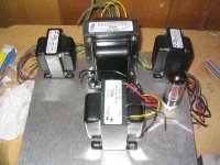
I'd rearrange the iron along the longer dimension so you can get your OPT's further away from the power transformer. It may not be necessary, and the level of coupling may be minimal. But, if you have very sensitive speakers, it may be enough to be audible. You can also use shielding, but distance is best.
You may also consider putting the PS (power trans, choke, rectifier) on one corner and move the OPT's closer to the other corner.
This arrangement worked well for me: http://www.diyaudio.com/forums/attachment.php?s=&postid=883561&stamp=1143927224
All the AC stuff is on one side, making power entry, etc., separate from signal stuff. Remember my compulsion to cram stuff in tight? I did have to use some aluminum plate later on (not shown here) to get the last tiny bit of inductive hum out, so I would increase the distance between the power trans and the OPT if you can.
Sheldon
Excellent. Thanks for the tip.
I'll be working on a few things today. More photos / questions / insanity to follow.
Kofi
I'll be working on a few things today. More photos / questions / insanity to follow.
Kofi
Your present arrangement of mains transformer and output transformers is fine provided that you ensure that the output transformers have their centres on the centre line of the mains transformer, but as Sheldon says, distance helps greatly. How about moving the second mains transformer and rectifier to be behind the main mains transformer and output transformers? That way, you can keep the mucky stuff at the back.
How's this? what about the inputs / speaker binding posts? Where's the best place for them? I have them currently planned for opposite ends of the chassis (see attached) with the speaker outs being next to the OPTs but I know I might need to move them.
Please advise and admonish at will.
Kofi
Please advise and admonish at will.
Kofi
Attachments
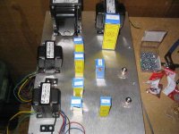
That looks better. As 8010 suggests, it's best to move your OPT's to the right a little and the power trans to the left, so that the centers of the three transformers are aligned. I don't think that this will make a major difference but it's easy to do. I assume that the big hunk of iron in the top right is a choke? If so, it should be ok there. Inductive coupling is primarily a function of current. The big current flows in the Power tranny are the filament windings. The AC current flow in the choke will be less too, so it should be fine there.
If you want your connections on the rear, you can do it this way: http://www.diyaudio.com/forums/attachment.php?s=&postid=883562&stamp=1143927353 , this shot is the same unit as shown before, but tipped on its back. You can see the inputs in the middle and the outputs on either side. Wires are well separated and crossed at 90 degrees. All AC wiring twisted and pushed to the edges as much as possible. This amp is more crowded than yours will be. Still, when I added some aluminum plate between the power trans and the first OPT, hum was undetectable, even with headphones.
Sheldon
Here is a little 6CK4pp amp I did. Not exactlly practicing exactly what I preach, eh? So, as 8010 said, you can also arrange things like your first try. This one is pretty quiet too, but I can tell the difference with or without shielding. So there is a little coupling. No hum with normal sensitivity (90ish) though. If you give yourself a little more room, and with that big honking choke, your amp should be very quiet, even with AC filaments.
Sheldon
Sheldon
Excellent! Thanks again!
Today's going to be a long one in the workshop. I'll hopefully finish drilling the chassis today. I may put the speaker outputs next to the RCA inputs on the right side of the enclosure. since the output signal will be running from the OPTs back across the EL84s to the right side, I'm assuming that the signal wires will need to be the hell away from the tube sockets when crossing over, eh?
Thanks again for all the advice. By the way--- no picture was linked / attached in your second post.
Kofi
Nice! Thanks!
Would it bee harmful to have the rectifier tube just behind the power transformer and choke? I'm afraid under my currrent layout theory that it will cause some hum in the ECC83 input tube on one of the channels.
Kofi
Would it bee harmful to have the rectifier tube just behind the power transformer and choke? I'm afraid under my currrent layout theory that it will cause some hum in the ECC83 input tube on one of the channels.
Kofi
- Status
- Not open for further replies.
- Home
- Amplifiers
- Tubes / Valves
- Kofi Annan in: "Push and Pull with Me"