Lots of soldering today. Star grounds make my projects look sloppy. Actually, my involvement in my projects makes my projects look sloppy.
Anyway, with regard to the inclusion of a potentiometer in the Bevois Valley design, should the input go directly to the left lug of the pot, and the center lug feed the 330R to grid and the 1M to ground?
Sorry to be so dense, but I think I've hit the wall on soldering time here.
K.....o......f...zzzzzzzzzzzzzzzzzzzzz.i.zzzzzzzzzzzzzzz
Kofi Annan said:Anyway, with regard to the inclusion of a potentiometer in the Bevois Valley design, should the input go directly to the left lug of the pot, and the center lug feed the 330R to grid and the 1M to ground?
And the "right" one to earth, yes. If looking the pot from behind (the inside chassis side)
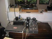
IT'S ALIVE!!!!!!
I have a moderately bad hum in one channel that I'll chase down later. It's one of these deals where when I turn the pot all the way on or off I get a funky ZZZZZZZZZZZZZZZZZZZ sound. I think there's a bad ground somewhere, but if you've got any ideas about that one, I'd love to hear it.
Right now, I just think it sounds so nice. Very detailed and a ton more bass than my SETs. Mingus's bass is really plucky and some of the glare I had before is all but gone now.
Thanks so much to SY, Sheldon, Johan and everyone else. This has really been a great project.
I'd show you the guts, but I'd just get embarassed. It's a better layout than I've had before, but it still ain't good.
More to follow as the amp breaks in.
Really, honestly, this is the greatest community. I just can't imagine doing this without your collective help and incredible patience. You've helped make me very happy and I appreciate that.
Kofi
Attachments
Kofi,
Something to look out for apart from the obvious - bad connections etc.
Your stating that you get that sizzle at either side of the pot reminds me of the possibility of feedback instability (oscillation) with a low input impedance. I do not have the Bevois V circuit in front of me, but look with a scope if you can. Placing (temporarily) a larger series resistor to the grid of the first tube (say 10K instead of the 330R if I read things correctly) - if that cures it, there is instability. (It manifests at either end of the pot becasue that is where you have low impedance to the input grid: direct to ground at one end or to a low feeding impedance at the other. In the middle of the pot you have the pot resistance in serie, thus it stops.) This as said, apart from more obvious reasons.
Regards.
Thanks! I think I understand this.
So, I'll start by checking signal grounds. Another symptom-- when drum beats get heavy, the speaker sort of farts and pops like it didn't have enough gas to finish the job and just gave up. The pop is pretty loud on loud passages with heavy dynamics.
This sound like anything you've experienced before?
Kofi
Forgot to mention-- I'm also getting a radio station on that bad channel. Does this sound any more like a bad ground to you?
Kofi
Kofi
I think Johan's suggestion of RF oscillation at the input sounds very likely. Try a grid-stopper as he says and see if it helps. Make sure the lead from the valve pin to the body of the resistor is really short - 1/8" is fine. Glad to hear your project is finally alive...
OK-- so I found part of the problem... maybe.
I was resoldering the 300R input resistors to get them as close as possible to the pins and then both channels started doing the potentiometer ZZZZZZZZZZZsqueakpopcrunch. So I started to reassess the situation and here's what happened.
When I take the NFB resistor / capacitor out of the loop, the potentiometer squeak goes away completely. I seem to remember that the feedback loop needs to be short and mine is pretty long, as in, there's about a foot between the speaker binding posts and the input cathode for the E88CC, which may be causing oscillation, maybe?
Also, it looks like the buzz I'm hearing in the one channel may be independent of the squeak / oscillation issue. I'm continuing to persue this, but what are my choices with respect to the NFB?
Kofi
It might be the feedback is positive instead of negative.
Try inverting the output terminals of the output transformer. Keep the NFB resistor in the "live" side.
Gastón
Try inverting the output terminals of the output transformer. Keep the NFB resistor in the "live" side.
Gastón
OK, I'll try that, but I'm sure that I hooked everything up to the correct terminals. Could it be the length of the NFB loop?
Also, I added 50K log pots to as volume controls, but the first 2mm turn rattles the windows and the second turn detroys mankind, so 100K log pots would be better for me, right?
Also, what's the harm in running these without the NFB loop? Would I need to change the cathode bias resistors or is the NFB loop exclusive of that?
Getting closer, but still need help...
Kofi
Kofi Annan said:OK, I'll try that, but I'm sure that I hooked everything up to the correct terminals. Could it be the length of the NFB loop?
As long as you keep it away from noise sources and keep the R and C close to cathode (low impedance but higher than the output) everything should be OK.
Also, I added 50K log pots to as volume controls, but the first 2mm turn rattles the windows and the second turn detroys mankind, so 100K log pots would be better for me, right?
IMO, there is something wrong here. 50K or 100K are OK. But it seems you either have too much gain or you are feeding it with too much signal. If you are using a line-level device to feed the amp (I suspect you are) then you have too much gain... check if the component values associated to the NFB loop are OK. Positive feedback could be messing here too...
Also, what's the harm in running these without the NFB loop?
first 2mm turn rattles the windows and the second turn detroys mankind... 🙂
BTW... how sensitive are your speakers ?
Gastón
BTW... how sensitive are your speakers ?
Good question. I'm using Fostex 206Es in a backhorn. They're 96dB out of the box and maybe a bit better in the horn enclosure, so this is hopefully the issue. I'd like to continue to use these with the amp, but I need to de-sensitize-i-fy the volume control.
So, I'll experiment with the NFB loop and see what I can come up with. All of the RF noise is gone as well, so it seems that the NFB was the culprit in both instances. I'll try and keep it way the hell away from everything and see what we get.
Thanks!
Kofi
Kofi Annan said:...... but the first 2mm turn rattles the windows and the second turn detroys mankind .....
Oh Oh Oh
 Something very wrong here. Methinks, either you have a totally bum pot (I believe yours are new) or from somewhere there is dc getting onto the input grid. Is this possible? Easy to check over the pot with a DVM.
But this could still be instability. You mentioned curing this - is the "pot noise" still there after the cure?
Running without NFB will of course give too much gain, and is not a solution - the NFB is there to get distortion down. (This is getting difficult, not being there to see what a scope shows.) About the question of long wires: The length is not so much the thing (talking within practical limits) than where you run it. Is your output leads away from any inputs, also the NFB lead. Again, pardon me for being lazy and not run back through all the posts to see whether you have access to a scope; it might become rather necessary as you run into more complex problems. Any hope there?
Regards
(PS: My search abilities seem to run low on this Sunday night. Will somebody please provide a link to the Bevois Valley circuit diagram? Thanks!)
Oh Oh Oh Something very wrong here. Methinks, either you have a totally bum pot (I believe yours are new) or from somewhere there is dc getting onto the input grid. Is this possible? Easy to check over the pot with a DVM.
I checked the pots and they seem OK. I can check for DC on the input grid, though.
But this could still be instability. You mentioned curing this - is the "pot noise" still there after the cure?
Nope. Pot noise is gone and all RF interference noise is gone too. Sounds dead quiet even on 96dB horns.
Running without NFB will of course give too much gain, and is not a solution - the NFB is there to get distortion down. (This is getting difficult, not being there to see what a scope shows.) About the question of long wires: The length is not so much the thing (talking within practical limits) than where you run it. Is your output leads away from any inputs, also the NFB lead. Again, pardon me for being lazy and not run back through all the posts to see whether you have access to a scope; it might become rather necessary as you run into more complex problems. Any hope there?
I'll try and re-run the NFB loop to and get it well away from all other noise-bearing components.
I do not have access to a scope and it's unlikely that Mrs. Annan is out getting me one right now, so I'm stuck with what I've got, which isn't much.
The Bevois Valley schematic is in Morgan Jones' Valve Amplifiers and might be a copyright thingee to post this here. If it's not a problem, I can mock up a schematic and post it.
I'm running it now with after a phono pre that does not have as much gain as a line-in CD player, so there's a better feel to the volume control, but I know I need the NFB back in. I'll work on that.
Kofi
I'll be working on the NFB issue this week as I am now out of time for the weekend, but I just wanted to note that this is an extremely dynamic amplifier. Tons and tons of detail and, even without NFB, it seems very precise.
Nice design.
Kofi
Nice design.
Kofi
No. I am not using shielded wire for the feedback loop. If I need that, I can do it, but what's the easiest way to sheld the wire? Can I get some appropriate sheilded wire from the local Home Depot / Radio Shack?
Of course, using shielded wire for the feedback loop would be obvious to everyone but me. Of course.
Hey-- I'm getting better. Last year at this time I'd be asking about the best way to put out an electrical fire!
Kofi
Of course, using shielded wire for the feedback loop would be obvious to everyone but me. Of course.
Hey-- I'm getting better. Last year at this time I'd be asking about the best way to put out an electrical fire!
Kofi
Shielded wire is a nicety for NFB loops, but classic amplifiers cheerfully had 12" runs of unshielded wire without any problems (after all, your loudspeaker cables are routinely unshielded).
Sounds to me as though you accidentally have positive feedback, rather than negative. Do you have the volume control turned down lower with feedback applied? If so, you've applied positive feedback by accident. Just swap the signal feeds to the grids of the output valves.
Sounds to me as though you accidentally have positive feedback, rather than negative. Do you have the volume control turned down lower with feedback applied? If so, you've applied positive feedback by accident. Just swap the signal feeds to the grids of the output valves.
Kofi Annan said:No. I am not using shielded wire for the feedback loop. If I need that, I can do it, but what's the easiest way to sheld the wire? Can I get some appropriate sheilded wire from the local Home Depot / Radio Shack?
Of course, using shielded wire for the feedback loop would be obvious to everyone but me. Of course.
Hey-- I'm getting better. Last year at this time I'd be asking about the best way to put out an electrical fire!
Kofi
I've seen amp done both ways with good results and was just curious as to what you were using.
Shielded wire should prevent the pickup of RF signals and I can't think of a good argument against using it. Since the feedback loop seems to be where your problems are coming from I think I'd give it a try.
I bought a spool of single conductor shielded wire at Radio Shack, it was a 50' spool IIRC. I use it for all my small signal connections (input jacks to selector switch to pot to input tube). Last time I was there they didn't have any more but they did have two conductor shielded wire, also in spools.
Shielded CAT 5 should work but you really only need one conductor (not counting the shield of course which should be grounded at only one end).
- Status
- Not open for further replies.
- Home
- Amplifiers
- Tubes / Valves
- Kofi Annan in: "Push and Pull with Me"