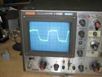
Next thing to do is ti stretch out the time base a bit and look at the oscillation frequency. At least it ain't rail to rail....
No mercy.
Crosstalk from one channel to the other is normal and only superb layout significantly reduces it (and it's always worse at HF). Genuine HF oscillation, on the other hand, needs to be rooted out and stamped upon. As previously suggested, a good start is to measure the frequency of the oscillation. Then break the global feedback loop and see if it goes away. If not, start working through the amplifier to see where it appears.
Crosstalk from one channel to the other is normal and only superb layout significantly reduces it (and it's always worse at HF). Genuine HF oscillation, on the other hand, needs to be rooted out and stamped upon. As previously suggested, a good start is to measure the frequency of the oscillation. Then break the global feedback loop and see if it goes away. If not, start working through the amplifier to see where it appears.
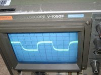
OK-- so Kofi did a little investigation today and it seems that the feedback is playing a substantial role in the crappy square wave. With the feedback disconnected, here's the new square wave.
I admit it still sucks and all, so I'll need to know how to fix this problem, but my greater concern is how I'm going to keep the feedback instituted and get rid of the oscillation.
Take a look and let me know what you think.
Kofi
I admit it still sucks and all, so I'll need to know how to fix this problem, but my greater concern is how I'm going to keep the feedback instituted and get rid of the oscillation.
Take a look and let me know what you think.
Kofi
Attachments
It's easier than you think...
Well, the feedback is trying to clean up that square wave, but it's not set quite right, so it's adding a little oscillation of its own. What you need to do is to destroy a couple of Mrs Annan's oldest and favourite medium wave radios by stealing their tuning capacitors. Then, remove the shunt capacitors across the output valve grid-leaks, and remove the existing feedback capacitor. Add one section of Mrs Annan's finest across the feedback resistor, then one section of the other tuning capacitor in series with a 10k linear variable resistor across the anode load of the first stage. Twiddle until you get a nice square wave without oscillation. Use an insulated knob on the capacitor connected to the anode load as it potentially has 285V on it. Be very careful.
Then, without disturbing the settings, turn everything off and desolder the tuning capacitors and variable resistor. Use your DVM on its resistance range to measure the variable resistor, and on its capacitance range to measure the capacitance. What, it doesn't measure capacitance? Time to buy a nice old-fashioned LCR bridge (best solution), or another DVM with capacitance range (not so good, but you can't have too many DVMs).
Note also that the feedback loop is in parallel with the cathode bias circuit in the Bevois Valley design. This means that by disconnecting the feedback circuit, I am altering the cathode bias somewhat, which may be causing some square wave error.
Also, I reworked the feedback circuit to reduce the NFB somewhat. I had to ensure that the cathode boas remained the same, however, so now the feedback loop consists of a 4.7K resistor bypassed by a 470pf mica cap. The cathode bias resistor was changed to a 700R.
The cathode voltage is correct, so I'm concluding that I got the bias correct. I wonder if I didn't hose the feedback upon recalculation, however, which would account for the oscillation.
Help.
Kofi.
Tweaking might have slightly upset the HF stability, but not by much. The real cause of your problem is that your output transformers etc are different.
Hi Kofi,
The tweeter as a load will not cut it. It is reactive. You need a pure a resistive load. Get thee to a Radio Shack and get something. The 8 ohm 20W were a stock item If they don’t have them get creative see what big white power resisters they do have and can you series/parallel them to get roughly 8-16 ohms, Oo parallel a bunch of 330 or 470 ohm ½ watt to get down to 10 ohms or so. So what if they get hot. this is quick and dirty DIY my man…John
The tweeter as a load will not cut it. It is reactive. You need a pure a resistive load. Get thee to a Radio Shack and get something. The 8 ohm 20W were a stock item If they don’t have them get creative see what big white power resisters they do have and can you series/parallel them to get roughly 8-16 ohms, Oo parallel a bunch of 330 or 470 ohm ½ watt to get down to 10 ohms or so. So what if they get hot. this is quick and dirty DIY my man…John
Re: It's easier than you think...
Wow. OK-- I think I actually understand this.
I have an old Kenwood receiver with an AM / FM tuner from which I can extract the variable capacitor. That would do the trick, right?
Bagging a 10K variable resistor should be no problem, but I'm curious-- why would I need to remove the shunt capacitors across the output valve grid-leaks? I know you're right here, I'm not challenging. I just would like to know why leaving these in would result in a skewed analysis.
Just want to learn, here.
That's interesting... so would "better" OPTs not be as much of a problem? Morgan Jones used some OPTs from an old Leak unit, so I should suppose that these are a cut above your bottom-rung Hammonds.
Again-- trying to learn here.
OK-- will do. I'll bag some resistors and measure again.
Thanks,
Kofi
EC8010 said:Well, the feedback is trying to clean up that square wave, but it's not set quite right, so it's adding a little oscillation of its own. What you need to do is to destroy a couple of Mrs Annan's oldest and favourite medium wave radios by stealing their tuning capacitors. Then, remove the shunt capacitors across the output valve grid-leaks, and remove the existing feedback capacitor. Add one section of Mrs Annan's finest across the feedback resistor, then one section of the other tuning capacitor in series with a 10k linear variable resistor across the anode load of the first stage. Twiddle until you get a nice square wave without oscillation. Use an insulated knob on the capacitor connected to the anode load as it potentially has 285V on it. Be very careful.
Then, without disturbing the settings, turn everything off and desolder the tuning capacitors and variable resistor. Use your DVM on its resistance range to measure the variable resistor, and on its capacitance range to measure the capacitance. What, it doesn't measure capacitance? Time to buy a nice old-fashioned LCR bridge (best solution), or another DVM with capacitance range (not so good, but you can't have too many DVMs).
Wow. OK-- I think I actually understand this.
I have an old Kenwood receiver with an AM / FM tuner from which I can extract the variable capacitor. That would do the trick, right?
Bagging a 10K variable resistor should be no problem, but I'm curious-- why would I need to remove the shunt capacitors across the output valve grid-leaks? I know you're right here, I'm not challenging. I just would like to know why leaving these in would result in a skewed analysis.
Just want to learn, here.
The real cause of your problem is that your output transformers etc are different.
That's interesting... so would "better" OPTs not be as much of a problem? Morgan Jones used some OPTs from an old Leak unit, so I should suppose that these are a cut above your bottom-rung Hammonds.
Again-- trying to learn here.
The tweeter as a load will not cut it. It is reactive. You need a pure a resistive load. Get thee to a Radio Shack and get something. The 8 ohm 20W were a stock item If they don’t have them get creative see what big white power resisters they do have and can you series/parallel them to get roughly 8-16 ohms, Oo parallel a bunch of 330 or 470 ohm ½ watt to get down to 10 ohms or so.
OK-- will do. I'll bag some resistors and measure again.
Thanks,
Kofi
Savaging the Kenwood will be start. You need two separate variable capacitors. The Bevois Valley circuit used Leak output transformers, they may be better (or worse) than Hammonds - but they're certain to be different. If you're going to set custom compensation to match your output transformers, you must remove all existing compensation, hence removing those capacitors.
By the way, if a tweeter is damped with ferrofluid it is very nearly a resistive load.
By the way, if a tweeter is damped with ferrofluid it is very nearly a resistive load.
Savaging the Kenwood will be start. You need two separate variable capacitors.
Yeah. I re-read the post and figured out I would need two. Luckily, I have an old Pilot AM / FM receiver that I have previously scavenged for parts, so I'll yank that one as well.
I've been thinking about your diagnostic instructions and I have a question or two:
...remove the shunt capacitors across the output valve grid-leaks, and remove the existing feedback capacitor
Got that.
Add one section of Mrs Annan's finest across the feedback resistor...
Understood.
...then one section of the other tuning capacitor in series with a 10k linear variable resistor across the anode load of the first stage
Whoa. Let's stop there. This confuses me. Not because it's objectively confusing, you understand-- it's because I ain't got good brains.
So, the first stage is the E88CC that's used as a phase splitter / driver stage for the EL84s. Given that, is the anode load you're referencing the 47K resistor for the first section of the E88CC or the 22K job for the second section?
Also, let's say that I have done as discussed, fiddled appropriately and now have an acceptable square wave. The measured value of the variable capacitor that bypasses the feedback resistor will obviously be the value of the feedback bypass cap required.
What will the variable resistor / variable capacitor values across the anode load tell me? The correct value for the shunt capacitors? What about the resistance measurement?
Sorry for the dumb ones here. They don't have good schools where I live so it kinda ain't my fault anyways.
Kinda.
Kofi
Given that, is the anode load you're referencing the 47K resistor for the first section of the E88CC or the 22K job for the second section?
The 47k from the first section. For the phase splitter to work properly, the plate and cathode loads have to be equal.
There's a very nice explanation of this procedure in "Building Valve Amplifiers."
The 47k from the first section. For the phase splitter to work properly, the plate and cathode loads have to be equal.
Got it. Thanks.
There's a very nice explanation of this procedure in "Building Valve Amplifiers."
Yep. Probably should have checked there.
So, based on the Rogers Cadet III design referenced in BVA, it looks like the variable capacitor across the load resistor is a supplement for the shunt capacitors across the output valves' grid leaks (disconnected for testing) as these act like like they're shunting the load resistor.
So, given that the variable capacitor would be replacing the other shunt caps, would I then need to halve the imputed value and use this as the shunt cap value for the output stage's grid leaks? There are two shunt capacitors (one on each output valve) and I'm thinking I'll either need to halve or double the capacitance value I derive.
Concerning the variable resistor across the anode load, I'm not sure what I'm deriving here. The variable resistor is in series with the variable capacitor and they're both bypassing the anode load, but once I discover what the proper resistor value is, I don't know what to do with it on account of I'm not that bright.
I know these are probably easy questions, but I have this track record of not getting it until it hits me in the face.
So hit me in the face already.
Kofi
OK, don't worry about those caps from the phase splitter (the second stage). I think they're probably superfluous anyway. We're just talking about the series RC across the plate resistor of the first stage; that's what you need to readjust from the original.
Gotcha, but here's a scenario:
Let's say I find that paralleled resistor / capacitor combo thats bypassing the load resistor is 2K / 210pF. Remembering that the grid leak shunt capacitors from the power stage (EL84s) have been disconnected during this process, do I need to:
a. reconnect the grid leak shunt caps for the power stage and add a paralleled 2K resistor and 210pF cap paralleling the load resistor (not likely, I'd guess)?
b. leave the grid leak shunt caps disconnected and add a 2K resistor and 210pF cap paralleling the load resistor (seems right, but what do I know)?
c. add a 2K resistor in parallel with the load resistor and add a ~105pF (210pF / 2) cap as grid leak shunts to the EL84s on th power stage (maybe right-er as this was the original topology)?
d. same as above with e ~420pF on each EL84 (since I can't determine if the circuit is seeing these in parallel or in series)?
e. same as above with 210pF on each EL84 (since I'm even dumber than you expected and can't determine if the circuit is seeing these as one 210pF or doubled or halved)?
f. go to Best Buy, get a $200 Sony receiver and listen to XM radio for the rest of my rotten life?
g. Other ________________
There. Now you know the limits of my incompetence. Well, actually there's more, but I was holding back.
Kofi
If it were me (and lord knows, you oughta be grateful that it isn't), I'd go Option b.
If I were really, really squeamish about changing anything from The Holy Writ, Option a will work fine. But me, I have problems with authority, so I'd just get the compensation looking right (i.e., the series RC across the first stage plate load), not worry about slugging Poles (they're mean when you get them riled), button it up, pour a nice mojito, let the wife take care of the screaming baby, and listen to some tunes.
If I were really, really squeamish about changing anything from The Holy Writ, Option a will work fine. But me, I have problems with authority, so I'd just get the compensation looking right (i.e., the series RC across the first stage plate load), not worry about slugging Poles (they're mean when you get them riled), button it up, pour a nice mojito, let the wife take care of the screaming baby, and listen to some tunes.
OK-- so some experimentation today.
I hooked up the air capacitors / variable resistor as instructed and I'm beginning to understand a few things:
It looks like adjustments to the variable resistor regulate the spike on the leading edge of the square wave. More resistance makes the spike go down.
Also, I thought that the variable resistor would form a parallel resistor combination with the load resistor, so I initially didn't understand how this would be helpful. Now I know that this is incorrect and I believe that the variable resistor / variable capacitor in parallel with the anode load is acting a a sort of a filter.
I know my assessment isn't quite right, but I'm getting there.
The super-crazy oscillation appears to have diminished significantly, but I need more resistance to calm the initial spike on the square wave-- the 10K just isn't doing it. I added a 1.2K job I had laying around and we're closer, but not quite there yet. I need to head to the Rat Shack to pick up some additional high-wattage resistors to add in series (or maybe a 25K variable resistor).
Also, also, the actual vertical components of the square wave look thin and mostly straight, but the horizontals are a little "thick", which I believe indicates some oscillation. I'm guessing all of this needs to go away, but maybe some is normal?
Also, also, too, I found I had to parallel sections of the variable air capacitors to get any impact. Again, this may be OK, but some commentary here would be welcome.
I did this without a capacitance-o-meter, which I recently bought from eBay and may be here in the coming week. Once I get that, I should have some additional insight regarding the capacitance.
Anyway, that's the update. More to follow as I assemble the rest of the testing rig. Comments would be most welcome.
Kofi
Sounds as though you're going in the right direction. You don't need to worry about the power rating of the resistors (they're not passing any DC, so they won't dissipate much just from the signal), but you will need to make sure that the final polystyrene capacitors that you fit in place of your variable capacitors have 250V rating or more.
I would guess that the fur on the tops and bottoms of your square wave are hum. Try slowing your 'scope down and triggering it from "line". If it all becomes stationary, you know it's hum.
I would guess that the fur on the tops and bottoms of your square wave are hum. Try slowing your 'scope down and triggering it from "line". If it all becomes stationary, you know it's hum.
Thanks!
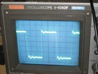
So, I added some resistance in series with the 10K variable deal, fiddled and got the attached square wave.
I think things look pretty good on the leading vertical edge (looks pretty straight) and on top, with the exception of some hum. The following vertical edge and the bottom look like they could use some improvement, however.
I guess at some point you just stop and say, "good enough". I'm thinking I may be close to that, but if the following edge / wave bottom are so troublesome that they need some attention, I'll keep pursuing it.
Also, I noticed that my plate voltage for the first stage is a little high-- about 310VDC. This could also be causing a problem, I'd guess, so maybe I need to drop a few more volts.
Comments?
Kofi
Attachments
- Status
- Not open for further replies.
- Home
- Amplifiers
- Tubes / Valves
- Kofi Annan in: "Oscillatin' in the Bevois Valley'"