I'd say > 16 Gauge. 10 Gauge may be excessive.
So noted. I'll grab some 14 AWG.
I think this either needs drawing out or you need to start to follow my command "think where the current will flow"
Following commands is what I do for a living. Unfortunately, the dense air in my cranuim has been limiting my understanding of this. That's why I continue to plague you. I have now drawn it out and I think it makes sense, but you know I'm coming back to the well again...
But in order to make sure everything is solidly referenced to the same place we connect signal return, heater supply return (negative heater line) and power supply return (negative HT line) together at the "star-ground".
OK. So the HT negative and the filament negative are NOT grounded in the PSU box. They are grounded to the second stage star ground in the phono stage box. This I got... I think. Remember that I will have two signal stage star grounds: one for the first stage and one for the second and the second stage will accept the B+ and filament "grounds".
Observe that although each current loop is joined to the star-ground ideally no current flows into or out of the starground but all are contained in their own respective loops.
Hmmm... This is really very interesting. I had never actually thought about this (not that its terribly surprising that I had never thought abouit something). So you're saying that the current flowing around in the closed loop for each stage's star ground will stay in that stage, right? So the whole purpose of the star ground is really to keep the current from the different stages from backing up into one another and causing stray electrons to be picked up as hum?
But, if I'm connecting the PSU grounds to the second stage and the second stage has signal grounds in it as well, how do the PSU grounds not contaminate the second stage signal? Maybe the dirty anti-parallel diodes have the answer!
Finally, as we do not have a seperate earth connector in our Neutrik speakon we need to make the earth connection somehow. We now tie the Phonostage chassis also to the star ground.
OK, so the phonostage chassis is tied to the star ground. If there are star grounds for each stage, then these are tied to one another with a low-impedance connection and then tied to the chassis using another low-impedance connection. I was going to uninsulate an RCA jack and use this as the star ground-to-chassis connection.
In the powersupply case the case is connected directly to earth (more preciceley the PEN - Protecteive Earth Neutral) but heater and HT supplies are NOT connected anywhere, EXCEPT for the back to back diodes which link the HT negative line and chassis.
OK, so the PSU chassis is attached to the third prong "Earth" wire. Got that. Then the heater and HT supplies are NOT grounded in the PSU box, right? So if the grounds for the HT and filament supplies are being passed to the phonostage box and they need to be grounded to the star ground in the phono stage box and NOT AT ALL in the PSU box AND if we need to make sure that these electrons stay in their own closed loop and don't contaminate the second stage where they are grounded, then it must be that the HT supply (ans possibly the filament supply as well?) is connected to the second stage star ground via the dirty, filthy diodes.
Right?
I feel a "wrong" coming on...
What this does is to keep the earth connection in effect disconnected from the HT supply if the difference in potential is small, so the earth loop normally introduced is in effect broken.
Which makes sense to me given the description you've laid out...
It is not that difficult really
Ha ha. Ha ha ha ha. Ha ha ha ha ha ha ha.
Ha
A ha ha...
All hysterical laughter aside, thanks so much for all your help with this. Why you would keep responding I have no idea. You must surely be exasperated by now. I think you could legally sue me for all the pain and suffering I have caused.
We need you on the UN Diplomacy Council.
Thanks again for all your wonderful help. Please let me know if I'm getting any closer to understanding this...
Kofi
Konnichiwa,
Make sure to screen the umbilical cable, BTW.
More or less good. They are referenced to the star ground of the TWO second stages (remember, your device is stereo).
Yes, ideally you would have a completely seperate supply for each stage and channel, as this is uneconomic we link first and second stage star ground. As the second stage draws more current and has higher levels of signal current modulation but less input sensitivity and given that there should not be any signal current be "escaping" from the first stage star ground; we feed the supply return to the first stage combined with the signal return, hoping that a short piece of wire between the stages and virtually no AC current flow will not cause us too many problems.
Ideally yes. In reality the impedances in the loop are never entierly zero, so some current "escapes" and flows along other routes, possibly causing undesirable effects.
Pretty much so.
Well, as the circuits we use have to combine supply currents and signal currents we have no choice, so therefore it is especially important to get the grounding arrangements right, because in this case we can keep supply and signal current loops as seperate as possible, joining only where unavoidable.
No, the diodes are only a device for electrical safety.
Yup, pretty much so.
Bad idea, use a seperate wire.
Yup, the two HT and two Heater wires are completely seperate from each other and the chassis (except for those 69 diodes).
So far so good.
Yup, you get a wrong.
Draw like this:
PSU box with the two pairs of wires (HT & Heater) coming out, not connected to anywhere but their respective supply sources, easily drawn as batteries.
Phonobox with the second stage star ground as well as +B line plus the two heaters of the valves (easily drawn as lamps) and the two wire pairs (HT & Heater) coming in, the HT negative goes to the 2nd stage star ground, the HT Positive goes to +B.
The heater negative connects to one side of each heater, the heater positive to the other. The heater negative is also taken via a short wire to the 2nd stage star ground.
FINALLY draw in the 69 Diodes inside the PSU Box between the HT negative line and the PSU enclosure and the Green/Yellow wire (PEN) is connected to the PSU enclosure at the same point as the 69 Diodes.
That's all.
I'm not all that litigious, donate a little to a childrens charity if you like for the trouble....
Nah, my approach to politics is way too Maoist and I have little patience.
("Political power grows out of the barrel of a gun." - Mao Tse Tung)
They would not like me stomping around there and just simply getting things done for a change....
Sayonara
Kofi Annan said:So noted. I'll grab some 14 AWG.
Make sure to screen the umbilical cable, BTW.
Kofi Annan said:OK. So the HT negative and the filament negative are NOT grounded in the PSU box. They are grounded to the second stage star ground in the phono stage box. This I got... I think.
More or less good. They are referenced to the star ground of the TWO second stages (remember, your device is stereo).
Kofi Annan said:Remember that I will have two signal stage star grounds: one for the first stage and one for the second and the second stage will accept the B+ and filament "grounds".
Yes, ideally you would have a completely seperate supply for each stage and channel, as this is uneconomic we link first and second stage star ground. As the second stage draws more current and has higher levels of signal current modulation but less input sensitivity and given that there should not be any signal current be "escaping" from the first stage star ground; we feed the supply return to the first stage combined with the signal return, hoping that a short piece of wire between the stages and virtually no AC current flow will not cause us too many problems.
Kofi Annan said:Hmmm... This is really very interesting. I had never actually thought about this (not that its terribly surprising that I had never thought abouit something). So you're saying that the current flowing around in the closed loop for each stage's star ground will stay in that stage, right?
Ideally yes. In reality the impedances in the loop are never entierly zero, so some current "escapes" and flows along other routes, possibly causing undesirable effects.
Kofi Annan said:So the whole purpose of the star ground is really to keep the current from the different stages from backing up into one another and causing stray electrons to be picked up as hum?
Pretty much so.
Kofi Annan said:But, if I'm connecting the PSU grounds to the second stage and the second stage has signal grounds in it as well, how do the PSU grounds not contaminate the second stage signal?
Well, as the circuits we use have to combine supply currents and signal currents we have no choice, so therefore it is especially important to get the grounding arrangements right, because in this case we can keep supply and signal current loops as seperate as possible, joining only where unavoidable.
Kofi Annan said:Maybe the dirty anti-parallel diodes have the answer!
No, the diodes are only a device for electrical safety.
Kofi Annan said:OK, so the phonostage chassis is tied to the star ground. If there are star grounds for each stage, then these are tied to one another with a low-impedance connection and then tied to the chassis using another low-impedance connection.
Yup, pretty much so.
Kofi Annan said:I was going to uninsulate an RCA jack and use this as the star ground-to-chassis connection.
Bad idea, use a seperate wire.
Kofi Annan said:OK, so the PSU chassis is attached to the third prong "Earth" wire. Got that. Then the heater and HT supplies are NOT grounded in the PSU box, right?
Yup, the two HT and two Heater wires are completely seperate from each other and the chassis (except for those 69 diodes).
Kofi Annan said:So if the grounds for the HT and filament supplies are being passed to the phonostage box and they need to be grounded to the star ground in the phono stage box and NOT AT ALL in the PSU box AND if we need to make sure that these electrons stay in their own closed loop and don't contaminate the second stage where they are grounded,
So far so good.
Kofi Annan said:then it must be that the HT supply (ans possibly the filament supply as well?) is connected to the second stage star ground via the dirty, filthy diodes.
Right?
I feel a "wrong" coming on...
Yup, you get a wrong.
Draw like this:
PSU box with the two pairs of wires (HT & Heater) coming out, not connected to anywhere but their respective supply sources, easily drawn as batteries.
Phonobox with the second stage star ground as well as +B line plus the two heaters of the valves (easily drawn as lamps) and the two wire pairs (HT & Heater) coming in, the HT negative goes to the 2nd stage star ground, the HT Positive goes to +B.
The heater negative connects to one side of each heater, the heater positive to the other. The heater negative is also taken via a short wire to the 2nd stage star ground.
FINALLY draw in the 69 Diodes inside the PSU Box between the HT negative line and the PSU enclosure and the Green/Yellow wire (PEN) is connected to the PSU enclosure at the same point as the 69 Diodes.
That's all.
Kofi Annan said:I think you could legally sue me fo all the pain and suffering I have caused.
I'm not all that litigious, donate a little to a childrens charity if you like for the trouble....
Kofi Annan said:We need you on the UN Diplomacy Council.
Nah, my approach to politics is way too Maoist and I have little patience.
("Political power grows out of the barrel of a gun." - Mao Tse Tung)
They would not like me stomping around there and just simply getting things done for a change....
Sayonara
Make sure to screen the umbilical cable, BTW.
Uhhh... need some help on this one.
More or less good. Yes, Ideally yes. Pretty much so. Yup, pretty much so. Yup, So far so good.
Everything seemed to be going so well...
Yup, you get a wrong.
Its like Paradise by the Dashboard Light, ain't it? Phil Rizzuto had me waved into home plate and then I get the "stop right there!!!'.
Draw like this:
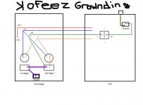
OK, I will then. Check out the attached pretty picture of grounding. Drawn with precision using an Industry Standard drafting program(me).
I think I had the right idea initially, but what blew my injured mind was that the HT- supply was attached to the unnaturally-acting diodes that were then attached to the Earth connection in the PSU box. I'm betting that once I ground the HT- supply in the phono stage box, this effectively gives me the safety ground I need back to the Earthed PSU box, right?
Please say right. I can see paradise by the dashboard light, here.
In case some aspects of the meticulously crafted drawing escape you, the brown wire in the PSU box represents the Earth ground. The square doo-dad in the PSU box are the sinful diodes with the AC connections shorted. The round thingees in the phonostage box represent the tube sockets.
[One question about the filament wiring-- I think I need to tie pins 4 and 5 together in the ECC83 and ground pin 9 rather than have the filament + on 4 and the filament - on 5. I know there's a reason I'm wrong on this, so let's hear it.]
That should explain everything in the draft image...
I'm not all that litigious, donate a little to a childrens charity if you like for the trouble....
I'll happily make a donation in your name to the Wayward Maoist Children's Fund. Kidding aside, I'll happily do this. Mrs. Annan and I give a regular contribution to a local charity which. next month, will be in your name.
Nah, my approach to politics is way too Maoist and I have little patience.
("Political power grows out of the barrel of a gun." - Mao Tse Tung)
They would not like me stomping around there and just simply getting things done for a change....
Hey! Actually it sounds like you'll get along great with the new UN ambassador from the US, John Bolton! What a guy!
Actually, I can legitimately appreciate Maoism. As my buddy Paul the Commie once said, "if you wanna make an omelet, ya gotta break a few eggs!".
Hopefully, this is correct, but as always, let me know if its not. I'd love to have understood this at last. I really would like to hear this thing someday...
Kofi
Attachments
Konnichiwa,
Yes, the -HT line brings throuh the Earth.
Your drawing is all right, EXCEPT, the bridge rectifier is wired wrong. Short the +/- terminals and connect one ~ terminal to the -HT line and the other to the chassis.
Learn to draw safety ground always as green/yellow.
this needs rotating by 90 degrees to work...
More or less. Remember, you do not ground the heater anywhere near there though, you just reference it to ground elsewhere.
So, short 4 + 5 together and connect it to +F and pin 9 to -F,
Maybe. More likely I'd just get my gun off and wire Dubya "send the next one in...".
Sayonara
Kofi Annan said:I think I had the right idea initially, but what blew my injured mind was that the HT- supply was attached to the unnaturally-acting diodes that were then attached to the Earth connection in the PSU box. I'm betting that once I ground the HT- supply in the phono stage box, this effectively gives me the safety ground I need back to the Earthed PSU box, right?
Yes, the -HT line brings throuh the Earth.
Your drawing is all right, EXCEPT, the bridge rectifier is wired wrong. Short the +/- terminals and connect one ~ terminal to the -HT line and the other to the chassis.
Kofi Annan said:In case some aspects of the meticulously crafted drawing escape you, the brown wire in the PSU box represents the Earth ground.
Learn to draw safety ground always as green/yellow.
Kofi Annan said:The square doo-dad in the PSU box are the sinful diodes with the AC connections shorted.
this needs rotating by 90 degrees to work...
Kofi Annan said:[One question about the filament wiring-- I think I need to tie pins 4 and 5 together in the ECC83 and ground pin 9 rather than have the filament + on 4 and the filament - on 5.]
More or less. Remember, you do not ground the heater anywhere near there though, you just reference it to ground elsewhere.
So, short 4 + 5 together and connect it to +F and pin 9 to -F,
Kofi Annan said:Hey! Actually it sounds like you'll get along great with the new UN ambassador from the US, John Bolton! What a guy!
Maybe. More likely I'd just get my gun off and wire Dubya "send the next one in...".
Sayonara
Your drawing is all right, EXCEPT, the bridge rectifier is wired wrong. Short the +/- terminals and connect one ~ terminal to the -HT line and the other to the chassis.
Will do. Should have remembered that.
So, short 4 + 5 together and connect it to +F and pin 9 to -F,
Got it.
More likely I'd just get my gun off and wire Dubya "send the next one in...".
That's exactly what true diplomacy requires. If you ever want a job at the UN, let me know.
Thanks again for all your fantastic help. I'll be wiring and soldering away this weekend and I'll post my progress. Not kidding about the donation either.
Thanks again,
Kofi
OK-- last question:
Should I ground pin 9 on either tube socket given that the filament negative supply will be independently grounded at the second stage?
Kofi
Should I ground pin 9 on either tube socket given that the filament negative supply will be independently grounded at the second stage?
Kofi
Konnichiwa,
On the ECC88 the heater is connected to pin 4 & 5 while pin 9 is a screen, which needs to be connected to "ground".
On the ECC83 the heater in connected to pin 9 and to pin 4 & 5 together, so no pin is there to be connected to ground, as they are already connected elsewhere.
Sayonara
Kofi Annan said:Should I ground pin 9 on either tube socket given that the filament negative supply will be independently grounded at the second stage?
On the ECC88 the heater is connected to pin 4 & 5 while pin 9 is a screen, which needs to be connected to "ground".
On the ECC83 the heater in connected to pin 9 and to pin 4 & 5 together, so no pin is there to be connected to ground, as they are already connected elsewhere.
Sayonara
OK-- so I "finished" this project today and, well, it doesn't work. No sound. Nothing.
A couple of problems. First, the filament was not seeing ground, which caused all sorts of problems. Initially, I had done as instructed:
On the ECC88, I connected f+ to to pin 4 and f- to pin 5 and grounded pin 9. On the ECC83, I connected pins 4+5 together and DID NOT ground pin 9-- I just left it alone.
Well-- filament voltages were all over the place. Once I checked and wsaw that the filament was not seeing ground, I grounded pin 9 on the ECC83 and things went back to normal.
Well, now I tried it again and I get the same thing. The filaments glow and the B+ is right where it should be-- around 245VDC. Both filaments are seeing 6.3V of regulated DC and everything seems to be connected properly. I'll take some plate voltage measurements and post them shortly.
Also, for the first time I insulated the RCA jacks. I had never done this before, but I have to wonder if I'm not sending the signal directly to ground so it never runs through the circuit. The jacks are not touching the plate and are grounded directly from the grounding tab to their respective stages' star grounds.
Man, it sucks to be at the precipice and not be able to finish it off.
Any help would be greatly appreciated. This is cutting into my drinking time.
Please help.
Kofi
Konnichiwa,
BAD IDEA.
You where supposed to connect pin 9 to -F.
BUT YOU WHERE NOT SUPPOSED TO GROUND IT.
As it should be.
Please check you wiring and first make sure you really understand what you where supposed to have wired.
Take a little break before looking at it again though.
Sayonara
Kofi Annan said:On the ECC88, I connected f+ to to pin 4 and f- to pin 5 and grounded pin 9. On the ECC83, I connected pins 4+5 together and DID NOT ground pin 9-- I just left it alone.
BAD IDEA.
You where supposed to connect pin 9 to -F.
Kofi Annan said:Well-- filament voltages were all over the place. Once I checked and wsaw that the filament was not seeing ground, I grounded pin 9 on the ECC83 and things went back to normal.
BUT YOU WHERE NOT SUPPOSED TO GROUND IT.
Kofi Annan said:Also, for the first time I insulated the RCA jacks. I had never done this before, but I have to wonder if I'm not sending the signal directly to ground so it never runs through the circuit. The jacks are not touching the plate and are grounded directly from the grounding tab to their respective stages' star grounds.
As it should be.
Please check you wiring and first make sure you really understand what you where supposed to have wired.
Take a little break before looking at it again though.
Sayonara
BAD IDEA.
You where supposed to connect pin 9 to -F.
Sorry-- should have mentioned that I DID actually connect pin 9 to -F, but the filament did not see ground. Shouldn't it have seen ground through the grounding of pin 9 on the ECC88?
If I need to disconnect the ground from pin 9 on the ECC83, I will, but this was the only way I could get the filament to see ground. I know I'm killing you here, but I just don't understand why the filament was not behaving as though it were grounded.
As information: my plate voltages are as follows"
ECC83 -- anode 1: 88.5V / anode 2: 98.5V
ECC88 -- anode 1: 77V / anode 2: 68V
Looking now to see if these make sense. Sorry to have not followed instructions on the filaments, but I'm puzzled as to how f- it will see ground.
Any help would be appreciated.
Kofi
OK-- now that I think about it, I think I understand why the filament was not seeing ground. Maybe It wasn't supposed to. I think that by connecting the ECC83 to ground I screwed up the voltage reference.
If this is correct, then I suppose its possible that I blew a tube. Once the filament became grounded, the voltage jumped up to about 10V instead of the 6.3V I should have seen and it likely fried a tube or two, right?
Most folks learn the normal way. I just can't learn anything until I break something.
Can you confirm?
Kofi
Kofi Annan said:
Most folks learn the normal way. I just can't learn anything until I break something.
Kofi
Like Sudan, for example.
Like Sudan, for example.
See? I can play the straight man once in a while! I don't always have to be Costello; I can be Abbott too!
Doesn't help me right at the moment, though. Any ideas on my predicament. I'm researching as well, but it always helps to have a guiding hand.
Unless it touches you in a secret place.
Then its not so fun.
Kofi
Kofi
I rewired mine to the grounding scheme that KYW suggested a couple weeks ago. Quietened down the noise to almost imperceptible levels.
Re-read the thread you will find that F+ goes to pin 4&5 connected together, F- goes to pin 9 on the ECC83. On the Ecc88 F+ goes to pin4 as you've done, and F- goes to pin 5 as you've done.
Then you ground pin5 on the ECC88 to the ECC88 star ground with the pins 3&8 and the 1M, 10M and 22uF. These are all connected together near the ECC88 valve. THis star point is then connected to the ECC83 star point which is grounded at the chassis.
Pin9 on the ECC88 is not connected to anything.
If you then connect your meter -ve to the chassis and the meter +ve to pin 4 on the ECC83 you should get 6.3V. Connect the meter +ve to pin4 on the ECC88 you should get 6.3V. ANy different you've done something wrong.
Kev
KevinTams said:Re-read the thread you will find that F+ goes to pin 4&5 connected together, F- goes to pin 9 on the ECC83. On the Ecc88 F+ goes to pin4 as you've done, and F- goes to pin 5 as you've done.
Then you ground pin5 on the ECC88 to the ECC88 star ground with the pins 3&8 and the 1M, 10M and 22uF. These are all connected together near the ECC88 valve. THis star point is then connected to the ECC83 star point which is grounded at the chassis.
Pin9 on the ECC88 is not connected to anything.
If you then connect your meter -ve to the chassis and the meter +ve to pin 4 on the ECC83 you should get 6.3V. Connect the meter +ve to pin4 on the ECC88 you should get 6.3V. ANy different you've done something wrong.
Kev
OK-- just fixed that. Both filaments are checking out fine and I still get no sound. I believe the filament issue is resolved, but I wonder if I blew a tube. Both filaments are lit, but that may not mean they're not blown.
Bright side: NO HUM!
I'm going to keep investigating, but any other recommendations would be most welcome.
Kofi
Konnichiwa,
These look more or less right, as said check the signal wiring...
Sayonara
Kofi Annan said:As information: my plate voltages are as follows"
ECC83 -- anode 1: 88.5V / anode 2: 98.5V
ECC88 -- anode 1: 77V / anode 2: 68V
These look more or less right, as said check the signal wiring...
Sayonara
Sorry I'm such a dumbass. I double checked everything and it all looks OK. I'll have a look at it in the morning with a clearer head.
It may be a blown tube. Can the filaments still light if the tube is bad? I'm just thinking that I may have blown one since the filament DC was too high initially when I fired it up.
All part of the learning process. I can't believe how much I've learned during this project. Thanks so much for being patient with me. I'll post my clearer-headed evaluation tomorrow.
Kofi
If the tubes were bad, you'd most likely not have those anode voltages. Check signal wiring, as Thorsten suggests.
Well-- new morning. Clear head. Actually, its more of a hungover head, but whaddaya want?
So, I planned to retrace the entire schematic, but that journey came to an abrupt end when I got to the third passive component and realized I LEFT OUT THE MOTHERFATHER ANODE LOAD RESISTORS FOR THE INPUT STAGE!!!!! Apparently you're not supposed to have any parts left over when you're done.
Quick solder here. Quick solder there. Plugged in and...
Beau-T-ful music. Leonard Nimoy's version of "You Light Up My Life" never sounded better.
There is absolutely no trace of hum at all. Gone. Completely gone. And the sound: Wow. I am absolutely floored by how good this thing sounds. I will never disobey Thorsten's instructions again. Well, maybe just once in a while-- the ALL CAPS RESPONSES crack me up sometimes.
I could opine breathlessly on how it sounds and use all the cool audio words (transients, vocal sibilants, punch, et. al.), but you know the deal, right? It just sounds great.
Thanks to all who helped, most notably Thorsten. You can't imagine how much I appreciate your patience and guidance. I really owe you big time.
I'll have some photos soon. Be prepared to be unimpressed with the aesthetics. Its a pretty utilitarian look overall (which appeals to Mrs. Annan), but it works and that's what's important to me.
To anyone looking to build this phono pre, please don't hesitate. Use Thorstens grounding technique for sure. That's advice from a UN Secretary General who did it the wrong way first. Check the first few posts in the thread and you'll see why you need to do it using the Thorsten method. Hummmmmmmmmm.
I really think the outboard power supply helps as well, so I'd advise that. Besides, it looks cool to have two boxes instead of one with the Speak-On connector running between the two. And DON'T FORGET THE ANODE LOAD RESISTORS!
Now, on to the next project. Check the "Push and Pull With Me" thread for more updates on Kofi's antics in the unfamiliar world of DIY tube audio. Its like a spinoff thread. Its "Joannie Loves Chachi" to this thread's "Happy Days". You know, Mr. and Mrs. C will probably show up from time to time. The Fonz too. But overall, you know it will never be the thread that this one was.
You can just feel it.
Thanks again. Honestly.
Kofi
Konnichiwa,
I think you are refering to the resistors leading from the Anode to rest of the signal circuit, not the actual anode load resistors.
And yes, if you have parts left over when finished you are usually in trouble.
If you feel my help was worth something my might want to consider to give a small charitable donation in my name to a local charity helping children in need (one you feel really makes a difference, not the one with the biggest advertising budget) or alternativley to medecines sans frontieres, based on what you feel you can afford and feel my help was worth.
You are most welcome.
Sayonara
Kofi Annan said:I LEFT OUT THE MOTHERFATHER ANODE LOAD RESISTORS FOR THE INPUT STAGE!!!!! Apparently you're not supposed to have any parts left over when you're done.
I think you are refering to the resistors leading from the Anode to rest of the signal circuit, not the actual anode load resistors.
And yes, if you have parts left over when finished you are usually in trouble.
Kofi Annan said:I really owe you big time.
If you feel my help was worth something my might want to consider to give a small charitable donation in my name to a local charity helping children in need (one you feel really makes a difference, not the one with the biggest advertising budget) or alternativley to medecines sans frontieres, based on what you feel you can afford and feel my help was worth.
Kofi Annan said:Thanks again. Honestly.
You are most welcome.
Sayonara
- Status
- Not open for further replies.
- Home
- Amplifiers
- Tubes / Valves
- Kofi Annan in: "B+... PLUS!!!"