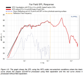
A few days ago I was chatting about on wall speakers in a thread and used the plots here to give an indication of the size of the wall interaction. The smoothing due to gating has removed the details and particularly the shape. Mind you the presence of the wall might cause one or two issues for a klippel-type measurement!
On wall might not be that bad, actually. Klippel does have a software add-in that allows measuring a 2 Pi environment, and it appears that such a measurement simplifies the modal analysis to a degree since some of the modes that would be present in a 4 Pi environment would not be present in 2 Pi. In fact, the paper in post 1,279 is all 2 Pi measurements, so hardware and software modifications to do that may be something to investigate eventually to add more value to this project.Mind you the presence of the wall might cause one or two issues for a klippel-type measurement!
Which just takes us back to Klippel's method.We don't really have to design much.
Just measure with the same microphone, move it a millimeter or so backwards, measure again and do the rest in post.
The point of my post was to offer an alternative that has the advantages I listed. It may turn out that Klippel's approach is the most practical, but simplifying the moving apparatus and cutting the measurement time in half are opportunities I find attractive.
This paper shows you can do a lot with two microphones and a solid spacerThe downside for us being the only device currently on the market that can directly measure the particle velocity of a sound wave is a Microflown sensor.
https://digitalcommons.mtu.edu/cgi/viewcontent.cgi?article=1951&context=etdr
I’ve returned from 1933 and have made a first pass at the paper on pressure gradient mics for speaker measurement. The main question that comes to mind is that if we wanted to use the pressure-velocity method (pressure and velocity measurements on one shell, rather than pressure measurements on two shells), can we get away with knowing only the velocity component along the radiation axis, or do we need to know all three velocity components? The p-p vs. p-v subwoofer measurement paper doesn’t use vector notation I recognize so I can’t tell. The 90-year old pressure gradient mic paper does seem to verify that velocity can be measured well by two closely spaced pressure mics. That can be done much more readily and cheaply now than it could then. If only the velocity along the radial direction is needed, then I think the pressure-velocity method has real promise.
Few
Few
I confess I was surprised by the assertion in that thesis that there should be a significant gap between the mics. I guess if the mics are mm apart, and the wavelength being measured is several meters long, then the pressure difference between the mics will be tiny, and the velocity measurement may get lost in the noise, even if the mics are aligned along the wave propagation direction.This paper shows you can do a lot with two microphones and a solid spacer
https://digitalcommons.mtu.edu/cgi/viewcontent.cgi?article=1951&context=etdr
Klippel uses simple gated measurements from the low kHz upward, so we already know there’s an upper limit on the sound field separation. I’m hoping that limited bandwidth allows the mics to be spatially separated so they can work together as a velocity detector, while still being close enough so that their spacing doesn’t conflict with the need for them to work up to the low kHz.
It’s interesting that even when starting with the pressure-velocity model in mind, the spaced mics idea seems to end up right back at the two concentric shells. I’m beginning to feel like Prometheus, although no bird would like the taste of my liver.
Few
This review from Amir makes me question that assumption. Here he only shows the computed measurements which are unreliable above 6 to 7 K. He says there are redundant measurements that show the unreliability but they are not used to make up for the problem with the computed result. I don't know if that is just a choice made or the way the software forces it to be.Klippel uses simple gated measurements from the low kHz upward,
https://www.audiosciencereview.com/...l-conceal-c83-invisible-speaker-review.53010/
I'm a bit unclear about what Amir means in that review. The legend of the first graph says red means "measured," which is then labeled "Actual" on the graph. The blue is labeled "Radiated" in the legend and "Computed" in the graph. Is "Actual" the gated result? Does the "Radiated" label not mean what was actually radiated?
In any case, when I viewed videos put out by Klippel some time ago, I'm pretty sure they said they just use simple gated measurements above some frequency. It's been awhile since I viewed those videos, but that's my recollection. I believe they said that at higher frequencies field separation breaks down, but it doesn't matter because gating yields reflection-free results anyway, and that's what is needed to determine the nearfield behavior. I don't remember what frequency they specified as the cutoff, but Amir's graph shows it to be around 2 kHz.
Plus I just found this graphic on the Klippel site:

That seems to make it clear that gating is used for field separation at high frequencies.
Few
In any case, when I viewed videos put out by Klippel some time ago, I'm pretty sure they said they just use simple gated measurements above some frequency. It's been awhile since I viewed those videos, but that's my recollection. I believe they said that at higher frequencies field separation breaks down, but it doesn't matter because gating yields reflection-free results anyway, and that's what is needed to determine the nearfield behavior. I don't remember what frequency they specified as the cutoff, but Amir's graph shows it to be around 2 kHz.
Plus I just found this graphic on the Klippel site:
That seems to make it clear that gating is used for field separation at high frequencies.
Few
Just only that review? lolI'm a bit unclear about what Amir means in that review.
The do this correctly is most definitely needs to be a sum of nearfield and relative far field measurements. Interesting that we get a fairly well presented bunch of measurements in that post. Above the 2k point is it still field separation? Os it it simply reflection time windowing? Or is it a hybrid?
I think the idea is that by gating out reflections you're left with only outgoing waves. Because the incoming reflections are eliminated by the gating the fields are effectively separated.Above the 2k point is it still field separation? Os it it simply reflection time windowing? Or is it a hybrid?
There are no far field measurements, they are all done near field. The field separation is simply not done on the data above some point, but the data is still fitted to the spherical harmonics.The do this correctly is most definitely needs to be a sum of nearfield and relative far field measurements. Interesting that we get a fairly well presented bunch of measurements in that post. Above the 2k point is it still field separation? Os it it simply reflection time windowing? Or is it a hybrid?
I meant exactly what you typed Few.I think the idea is that by gating out reflections you're left with only outgoing waves. Because the incoming reflections are eliminated by the gating the fields are effectively separated.
Not exactly. When you loudspeaker is producing test frequency wavelengths that are shorter than the distance to the microphone, or the reflective surfaces you are no longer in the nearfield. As you would be when you are a few millimeters away from the sound source. That was my reference between contrasting nearfield and farfield. A mic distance of 0.5 to 1 meter is going to incorporate a lot of spurious to the signal source room effects.There are no far field measurements, they are all done near field. The field separation is simply not done on the data above some point, but the data is still fitted to the spherical harmonics.
I admit that my concept of how the reflections can be subtracted and the actual math may be incompatible. As in Mark doesn't properly understand it.
In a nut shell I look at it as a cumulative comparison. A comparison between what was measured nearfield having little to no reflections, but having no useable data that can convey the directivity pattern of the loudspeaker. And then progressively measuring outwards, for simplicity's sake overlaying graphs and subtracting what is not in common. The room reflections will be the parts that will stand out different from an adjacent measurement. The same will work for room modes and frequencies that are under 2k. Over a sufficient physically large measurement area the room modes will be different enough to differentiate them from the unreflected source signal being emitted by the loudspeaker under test. That will allow a pseudo anechoic measurement akin to a time gated measurement
Last edited:
Agreed. A little more than plausible. Looks very like it is what is being done.Nothing is proven. Although I find it plausible.
The graphic shows a single axis as does Amir, what I don't see is a complete spinorama where the gated and computed measurements have been spliced. If this was a simple button press I imagine Amir would present it. Hence not bring sure. I also made the assumption that there was a gated splice but now I am not so sure. Not that it matters as I am not going to buy an NFS anywayThat seems to make it clear that gating is used for field separation at high frequencies.
(Unrelated to Klippel)Plus I just found this graphic on the Klippel site:
View attachment 1290966
It looks like if I can get down to 60Hz semi-anechoic with absorption then I’m “gold”.
- Home
- Design & Build
- Software Tools
- Klippel Near Field Scanner on a Shoestring

