I hope you get it sorted Jon!
Once the basics work you can have fun experimenting with grounding schemes! 😉
I have found (with 67.7% confidence) that if I connect the loudspeaker return cabling to the rectifier's grounding lug (case ground, I think) it sounds better than if I return the cables to the mid-point between the power supply caps (where I think it ought to go).
No idea why..
BTW, the original 405 has the speaker returns going to the grounding lug.
Keith Snook seems to change the grounding:
An externally hosted image should be here but it was not working when we last tested it.
Thanks for that photo Roger!
I think I understand why it sounds better with the speaker returns going to chassis ground: They will be nearer the OP-amp's "+" input, which is referenced to ground. BTW, the difference is large, I can say now after playing at normal volume levels. I was concerned about more channel intermodulation, but thinking about it some more I think that the global feedback loop will suppress that effect totally.
I wonder if a workable alternative solution to Keith's one would be to separate the OP-amp's "+" input ("+" due to the inverting input stage) at the point it would connect to board-ground, and connect that directly to the speaker output terminal ground? That way it would be undisturbed by larger currents and work as an almost pure sensing wire. I say "almost" as the "+" input is involved in filtering of the feedback circuit. I suspect this may be to invite ground loop problems though..
Hi,
Been looking in this thread for a while 🙂
Although nothing to do with Quad this helps show some of the effects of returning the load to the "wrong" point.
http://www.diyaudio.com/forums/showthread.php?s=&threadid=126370&highlight=
Been looking in this thread for a while 🙂
Although nothing to do with Quad this helps show some of the effects of returning the load to the "wrong" point.
http://www.diyaudio.com/forums/showthread.php?s=&threadid=126370&highlight=
Mooly said:Hi,
Been looking in this thread for a while 🙂
Although nothing to do with Quad this helps show some of the effects of returning the load to the "wrong" point.
http://www.diyaudio.com/forums/showthread.php?s=&threadid=126370&highlight=
Hi!
I read through your thread, and I think I may be proposing the opposite of what you are, but I'm not sure! I want to pollute the ground connected OP-amp input (negative input normally, but positive input on the inverting Quad) with the return-to-ground signal (i.e offset from true zero voltage at the terminal) from the loudspeaker. The theory being that any potential fluctuations due to ground impedance will then be compensated for by the OP-amp's differential input, hence creating more effective feedback accounting for both loudspeaker terminals, rather than primarily the "hot" one.
I found these two photos of yours very interesting:
http://www.diyaudio.com/forums/attachment.php?s=&postid=1561695&stamp=1216051363
http://www.diyaudio.com/forums/attachment.php?s=&postid=1561697&stamp=1216051521
Perhaps the large amplitude increase is due to the grounded speaker terminal potential moving (as it's not a true zero impedance point), and being compensated for in the feedback loop? (Not having seen your amp, I'm guessing now.)
Before trying out the neutral speaker terminal sensing approach I need to figure out if doing so constitutes positive feedback, blowing up the amp and/or the speakers..
Hello Patrik,
Erm !! It sounds good in theory, in practice 🙂 well.
What you are after is perhaps more like a 3 or 4 wire sensing system where the feedback is taken from the load itself. Lab PSU's often have this sensing arrangement, and it "removes" the effect of all the wiring/sockets etc.
If you look at he drawing below, which is any amp, discrete/chip/ Quad 405 etc there is one thing to remember. The amp will try and keep the voltage difference between it's inverting and non inverting terminals at ZERO. So if RF is 9 K and R1 is 1K and you put 1 volt on the input ( analysing at DC is surprisingly useful- each bit of wire and print in your amp has significant resistance ) then the output rises to 10 volts to do this. That 10 volt's gives 1 volt on the inverting input so we have our gain of ten. If we connect the output to point D the current in the load flows back to the PSU and does not contaminate the input.
Now imagine that blue ground has 1 ohm resistance end to end ( which is probably to high by a factor of 5 or 10 ).
Now if you connect the load along here at points A/B C etc it will alter the voltages seen by the amp. Point C will "add" a voltage to the inverting input that is in phase with the output.
Point B will add the signal to both input and feedback nodes but not equally. Why -- because points B and C have resistance between them creating a volt drop.
It get's even more interesting when the load is reactive as the current and voltage are not now in phase + the load ( speaker )has a very variable impedance curve maybe as low as 3 ohms and as high as 20 or 30 ohms.
It's no wonder the "sound" changes. There is really only one correct feedback and grounding scheme, and going away from this can increase the distortion of the amp by perhaps 10 to the point of instability !!
Same for the inverting configuration as well. Draw it out -- it makes it easier to visualise.
Regards Karl
Attachments

Thanks for your insights Karl!
I tested my theory a little bit, by going halfway: The 405 has an existing path from power caps middle (and star ground point) to chassi's ground, which connects to the DIN input as well as the ouput stage ground (via heat sink arrangement, as far as I understand). This path was augmented with a short and fat wire from loudspeaker neutral terminal directly to the channel's input side (small signal) ground. (Solder side, where the push-on pin for signal ground enters.)
The new low impedance path just does what a more complicated path already does, but far better I hoped. I wasn't very worried about oscillation etc since the path existed already. Since I didn't remove alternative paths there are potential ground loop problems, which I'll live with until I feel I understand what paths can be disconnected without bad things happening..
The result is encouraging. Very dynamic, very transparent sound. Really comes to life at life-like levels. I don't think the effect is due to overshot, as treble is very natural and not at all uncontrolled or exaggerated (and this is at very loud levels). Also, when only one channel had been modified, that side sounded slightly more recessed compared to the unmodded one. It's the best sound I've had so far in my system. The one obvious shortcoming is in bottom end power at very loud levels, where a few more 100W might help. Or maybe it's the current limiter that stops delivery..
Hi Patrik,
It's the great mystery in audio is it not !
If we were designing say a PSU then the only correct feedback connection is the one that totally and fully allows the feedback to compensate for all loads. A 12 volts PSU whose output rises slightly under load ( or falls ) because of an incorrect feedback take off point would be slated.
But what of audio -- if it "sounds better" through being "distorted" in some way. Where does that lead us ?
As I have said many times, it's no good telling everyone your system is so perfect, that, that is the reason why "most recordings" sound bad. What good is that if you don't actually like listening to it !
The quest continues 🙂
Right Karl!
However, I think the default grounding scheme in the 405 is far from optimal! I really think my changes are bringing it nearer to the optimum. I'll just need to verify with measurements as well. 😉
Regards
However, I think the default grounding scheme in the 405 is far from optimal! I really think my changes are bringing it nearer to the optimum. I'll just need to verify with measurements as well. 😉
Regards
Patrik,
Take it you have a 'scope and generator 🙂 Try this, see if the output alters at all under load ( say 3 or 4 watts output and dab a 5 ohm or similar across the output ). Measure at the NFB take off of course, not at the sockets. Also check that doing this causes no output from the other channel. When you load the amp any ground currents could be getting into the other channel and will show up as an unwanted output on that channel.
Regards Karl
Mooly said:Patrik,
Take it you have a 'scope and generator 🙂 Try this, see if the output alters at all under load ( say 3 or 4 watts output and dab a 5 ohm or similar across the output ). Measure at the NFB take off of course, not at the sockets. Also check that doing this causes no output from the other channel. When you load the amp any ground currents could be getting into the other channel and will show up as an unwanted output on that channel.
Regards Karl
Yes, I have a scope and generator.
I'll try the experiment, and report back.
Hi all,
I have just collected some links to other modifications of the Quad 405. Some of them seems includes the PSU and grounding.
Göran Finnberg: I have a schematic on one of his rebuilds of the 405. Is different from Bernd Ludwig's but it is similar as it is not just a substitution/removing of parts like Mod Squad Mac 405(look here: http://www.quad405.com/) or some of Dada's and Net Audio's modifications. I do not dare to present it here without Göran's permission.
Keith Snook: http://www.dc-daylight.ltd.uk/Valve-Audio-Interest/Schematics/QUAD-405-M12368-DCD-Mod-3-iss2.pdf This is my favorite! Based on Bernd Ludwig's modification but taken some steps further. I like the idea of removing all components that are not neccessary. Zsolt Vadaszi have made some boards based on this: http://twin-x.com/groupdiy/albums/userpics/dsc_0566_1.jpg
I have been asking Zsolt if he could make some changes to make his boards a bit more universal. I want them to look more like this: http://twin-x.com/groupdiy/albums/userpics/Quad405_20080622_1840.GIF My changes will allow different sized capacitors, there are additional electrolytics and transistors in the supply lines like in BernD Ludwig's schematic.
Dada Electronics:
http://quadrevisionspot.blogspot.com/2008/07/dada-announces-405-high-end-boards.html
http://cgi.benl.ebay.be/Quad-405-Hi...Z295QQtcZphotoQQcmdZViewItem#ebayphotohosting
Here information on their power supply: http://quadrevisionspot.blogspot.com/2007/01/installation-instructions-405-dual-psu.html
Here their replacement for the Quad clamp circuit: http://quadrevisionspot.blogspot.com/2008/03/dada-loudspeaker-protection-delay-pre.html
Net Audio:
http://www.net-audio.co.uk/quad405mk3.html
http://www.hi-fi-insight.com/303/net-audio-405-3-initial-review.htm
At the end of this page: http://www.net-audio.co.uk/405dmpsu.html you can also find a Quad 405 DMPSU Earth Strap .
Roger Gustavsson
PS. I have an Altium file from Zsolt Vadaszi's project. Maybe someone could modify it for me? I have also a contact in China willing to make some PCBs. Think it was about $20 / 4 PBCs.
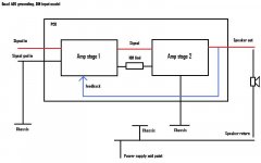
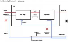
Modification 1, where signal input ground is more tightly bound to speaker return. In real life the wire is short. Shown here as fat and blue. Before the mod the same path existed via the chassis. (Still does, in this mod, in addition to the new path)
Attachments

What won't work ? Whats it doing ? Is this the amp you pictured right at the start.
If you can post a circuit might be able to help 🙂
If you can post a circuit might be able to help 🙂
As far as I can make out its a straight forward 405 (not 405-2) clone, I have someone looking at it at the moment to see what I have missed. I suspect its a problem with the Op-amp supply. Time will tell...
- Status
- Not open for further replies.
- Home
- Amplifiers
- Solid State
- Kit building Quad 405 Clone