JonLawes said:Ok, I'll invest in a toroidal to suit once I am sure they work. About 600VA should be ample shouldn't it?
Should be plenty enough!
You could go for two 300VA for a dual mono implementation.
By dual mono do you mean two channels, one per board? Normal Quad setup?
I was just going to run a transformer with a +50 and -50v rails, seperating each rail to the individual left and right channel boards.
I was just going to run a transformer with a +50 and -50v rails, seperating each rail to the individual left and right channel boards.
JonLawes said:By dual mono do you mean two channels, one per board? Normal Quad setup?
I was just going to run a transformer with a +50 and -50v rails, seperating each rail to the individual left and right channel boards.
A normal 405 has a single transformer, and two large caps after the rectifier bridge. So both the transformer and the caps are shared between the left and right channel boards.
You could use two diode bridges connected to 4 smaller caps (2 for each channel) to get better channel separation, or for even better separation, two trafos as well (only sharing the power cord). If you dont use a 405 case, you don't have to use smaller caps either!
I have just ordered two 22000uF caps to cram into a 405 case. They should fit OK. This doubles the original power supply capacitance. (No dual mono though, but I intend to do this with two amps and only use one channel in each amp.)
BTW, if you go for two trafos, you can of course split the thing into two cases too, should you so wish.
BTW, look out for the rating on the secondary voltage..
I'm very rusty now, but I suspect the secondary will be rated in RMS (as it's alternating), whereas the rectified voltage will be up at the peek level of the secondary voltage.. (RMS X 1.4)
Something like that.. If you don't know for sure, check with someone here who is more up to date than me!
I'm very rusty now, but I suspect the secondary will be rated in RMS (as it's alternating), whereas the rectified voltage will be up at the peek level of the secondary voltage.. (RMS X 1.4)
Something like that.. If you don't know for sure, check with someone here who is more up to date than me!
I'll bear that in mind, thank you. I'm planning to put quite a bit of effort into the design of the power supply so hopefully it won't be the weak point in the system.
For those who are interested (anyone? 😉 ) here is my current setup. Its all been bought on a tiny budget.
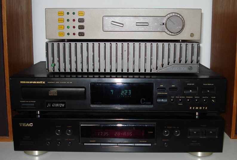
From top to bottom;
Quad 34 (Din inputs!) Bought cheapish on ebay, presumably because it was DIN. Approx £100.
Quad 306. Bought cheapish on eBay as its paint is chipped and awful. Still sounds beautiful though. Approx £120.
Marantz CD36. Won on eBay very very cheap as the cd drive no longer opened its drawer. Put new drive belt on and it worked a charm. A couple of years back I damped the cd drawer and case internals with silca-set (we use it on aircraft, I work in flight test) and just a few days ago fitted a 10p to the puck as mentioned on here!). Approx £7.10p!
Teac Tuner. Yes, another eBay bargain. approx £12.
Speakers: Celestion Ditton 15XR. Bought complete with Sony amp from a colleague for £20. Sony amp did good service until the quad arrived.
So my total system cost around £260, which I don't think is bad at all. I'm very happy with it, and have been gingerly exploring the internals with a bemused smile on my face for a while now!
For those who are interested (anyone? 😉 ) here is my current setup. Its all been bought on a tiny budget.
From top to bottom;
Quad 34 (Din inputs!) Bought cheapish on ebay, presumably because it was DIN. Approx £100.
Quad 306. Bought cheapish on eBay as its paint is chipped and awful. Still sounds beautiful though. Approx £120.
Marantz CD36. Won on eBay very very cheap as the cd drive no longer opened its drawer. Put new drive belt on and it worked a charm. A couple of years back I damped the cd drawer and case internals with silca-set (we use it on aircraft, I work in flight test) and just a few days ago fitted a 10p to the puck as mentioned on here!). Approx £7.10p!
Teac Tuner. Yes, another eBay bargain. approx £12.
Speakers: Celestion Ditton 15XR. Bought complete with Sony amp from a colleague for £20. Sony amp did good service until the quad arrived.
So my total system cost around £260, which I don't think is bad at all. I'm very happy with it, and have been gingerly exploring the internals with a bemused smile on my face for a while now!
Jon,
That's the exact amp I saw on ebay, and thought about buying myself, figuring it would be a good chance to try out a Quad cheaply! Then I figured I needed 100W, so went with a 405. I think they should sound pretty much the same however. So that amp is responsible for this entire new adventure (together with destroying my previous amp).
Got my 22000uF caps today, so hopefully they will go in tonight! The 405 seems to have reformed (at least partially) its power caps, so it's not too bad as it is. With the right material it sounds fantastic. Just excited to see what the difference will be, if any.
BTW, I love the size and looks of the preamp. I might get one like it just to play around with. Does need remote control added.
Got the EPCOS 22000uF caps in, in case anyone is interested.
I rerouted some of the wiring, without changing the topology. (Neutral speaker wires went to rectifyer's grounding lug, then a single thin wire went from there to the caps' mid point. Didn't make sense to me. Would create channel intermodulation. So I put the speaker returns right at the bar between the caps.)
Sound was extremely "dark" initially. After about 3 hours things started to change. I think the sound is still altering. Some magic from before went missing, and it sounded just like any other powerful solid state amp. Then I cranked the volume up a lot, and first it was edgy, then it suddeny mellowed and became magic see-into and musical/natural.. Wonder what is going on. Thermal effects? Parasitic oscillation?
Anyway, interesting to hear how power caps alter the sound, and changing as they "break in" ("form"?).
The sound has gelled nicely now!
Lot's of grunt combined with delicacy. Stable imaging even when bass and percussion goes mad.
The nasty edge earlier I now suspect was caused by mains noise. Likely our washing mashine! I'm thinking of ways to make the power supply more immune. Perhaps a second bank of caps separated by inductors.
Lot's of grunt combined with delicacy. Stable imaging even when bass and percussion goes mad.
The nasty edge earlier I now suspect was caused by mains noise. Likely our washing mashine! I'm thinking of ways to make the power supply more immune. Perhaps a second bank of caps separated by inductors.
You should concider some sort of filtering like this
http://www.diyaudio.com/forums/showthread.php?s=&threadid=104626&highlight=
Toroidal transformers are more sensitive to DC mains ofset
and this
http://www.diyaudio.com/forums/showthread.php?s=&threadid=11730&highlight=
even a filtered IEC socket can makes a big improvment.
Stuart
http://www.diyaudio.com/forums/showthread.php?s=&threadid=104626&highlight=
Toroidal transformers are more sensitive to DC mains ofset
and this
http://www.diyaudio.com/forums/showthread.php?s=&threadid=11730&highlight=
even a filtered IEC socket can makes a big improvment.
Stuart
Thank's for the suggestions Stuart!
I'll look into making an external line conditioner which also removes any DC. I do remember another amp's transformer starting to buzz whenever the washing machine was running. So perhaps the washer causes DC on the mains.
I'll look into making an external line conditioner which also removes any DC. I do remember another amp's transformer starting to buzz whenever the washing machine was running. So perhaps the washer causes DC on the mains.
Right, I have now constructed both boards (a few lunchtimes at work was all that was needed). I just want to do a last physical check that I have the transistors the right way round (the board was screen printed wrong) and I'll be ready to test. My bench at work can only supply +30 and -30 but I'm sure that will be sufficient for a test.
I was thinking about powering it up and then putting my ipod on the input and a speaker on the output (I have a spare pair of Maudaunt Shorts at work), using the ipod volume control to keep the input level down. Wang in the +/-30v and hide behind the bench whilst I turn it on...
Another thing I might do is move the fuse holders off board, I really don't like how close they are to each other.
Set your current limits on the psu to 250mA or the amp will not settle correctly
Before you connect the spk measure dc offset it should be under 5 or so mv if that ok then connect your spk
best of luck
regards Trev
Before you connect the spk measure dc offset it should be under 5 or so mv if that ok then connect your spk
best of luck
regards Trev
Bugger... the amp just hits current limit on the PSU on both channels; the output is pure noise too. I am going to scour the diagrams again but there isn't much to go on.
The kit was supplied with no wiring diagram, and the screen printing on the PCB has already proven to be incorrect in a couple of places. I'm not hopeful, and I don't really know enough to do much fault finding. Fingers crossed.
The kit was supplied with no wiring diagram, and the screen printing on the PCB has already proven to be incorrect in a couple of places. I'm not hopeful, and I don't really know enough to do much fault finding. Fingers crossed.
I am suprised that you have hit a problem ! what is your current limit set at
My units worked first time I obtained the schematics from the quad world web site and used the Mk1 drawing As for transistor markings as I did not use origional types I verified each pin out before soldering in and as explained modified a few values to take into acount the reduced supply rails
regards Trev
As designed and when operating from +/_50V supplies when the amp is driven into clipping its the opamp that clips and not the output stage. If you operate the amp from +/_30V the output stage may clip first and may not recover cleanly, if you also current limit the supply this will lower the supply further
Stuart
Stuart
So you think I need to increase the voltage? Maybe I'll finish the PSU side of the circuit and run it from that and see if that improves things.
Thanks for the advice, however scary it is!
Thanks for the advice, however scary it is!
Right, I have the Capacitors, I am looking at a transformer that seems OK and I have ordered the Bridge Rectifiers.
I would not expect the symtem you describe due to low voltage ! Check that the op amp rails are in the region 12-15 volts - on pin 4 +on pin 7
This varies on differant versions
Dont just up the rails and switch on it could be expensive !
I have repaired quite a few of these so don,t hesitate to contact me if I can help !!!
regards Trev
This varies on differant versions
Dont just up the rails and switch on it could be expensive !
I have repaired quite a few of these so don,t hesitate to contact me if I can help !!!
regards Trev
- Status
- Not open for further replies.
- Home
- Amplifiers
- Solid State
- Kit building Quad 405 Clone