Here is a Kingfisher schematic that should be fairly close to the final. I'm in the last stages of wiring the thing up, and will probably bring it up this weekend. As I said before, the circuit is kinda complex due to the inclusion of the cathode followers in front of the output stage. The input differential stage will drive the 7591As by itself. However, the extra tube halves were there, and I just had to gild the lily, so to speak. The delay in completion was due to a complete rewiring of the innards,as I was not satisfied at all with the first layout.
Attachments
Both channels are up and balanced, with the idle current trimmed to a nicety - I'm running about 35 ma per tube. This amp will be rather lovely in an austere way when it's all together. However, I'm still having oscillation problems when I attach a speaker load. I suspect that the loop response is far too zippy for its own good. 10kHz rise time into a resistive load is 5 usec or less. I notice no misbehavior at the output with a resistive load - it's only with the speakers that the amp loses its mind. It probably doesn't appreciate the extra capacitance from the speaker cables, not to mention whatever is going on in the crossover. I'm also noticing a fairly large amount of overshoot at my input stage. Three measures come to mind
1) Increase the gate stopper resistor on my input JFETs (currently at 1k). This fixed a vexing oscillation problem in my "Shrine" amp that has a single ended cascoded JFET input stage.
2) add an RC damper network between the two plates of the input stage (I'll save this measure for last).
3) Increase the value of the roll-off cap on the global feedback network.
I'll be trying variations of 1) and 3) to try and get the amp to be stable into a speaker load. Having done that, I can then think about buttoning it up so I can take it to work, where we have a gain-phase analyzer or two. Getting some concrete numbers regarding gain and phase margin would be helpful.
Huh - it figures that the one measure that I save for last (number 2) in my last post) is the one that works right off the bat. Adding 100pF + 4.7k in series between the two plates at the input stage tames the savage cascode and allows actual operation into real speakers without any evil behavior. I tried this using funky-a** Z5U disc caps 'cause that's all I had with the proper voltage rating. I go shopping tomorrow at the local surplus emporiums for some real caps with 500V rating - NPOs (not likely), mica, or polystyrene (yes there are some polystyrenes with 630V rating, though maybe not in the small values I'll be needing). I'll get an assortment of values and tune for well-behaved square-wave response for the inner loop.
What was happening was that the input stage was misbehaving and making like a push-pull oscillator, with the succeeding stages going along meekly for the ride. That's what I get for a spread-out input layout - next time around, I'll do a layout that puts the input JFETs and tube cascodes right next to one another without any tenuous interconnects. The output transformer was actually paring some of the high frequency nastiness off of the square wave response, so the closed-loop square wave response was a bit misleading. Anyway, I'll tune and tweak and report the final results soon. A few ventilation holes, and I can close up the box and move this puppy to the living room where it belongs.
What was happening was that the input stage was misbehaving and making like a push-pull oscillator, with the succeeding stages going along meekly for the ride. That's what I get for a spread-out input layout - next time around, I'll do a layout that puts the input JFETs and tube cascodes right next to one another without any tenuous interconnects. The output transformer was actually paring some of the high frequency nastiness off of the square wave response, so the closed-loop square wave response was a bit misleading. Anyway, I'll tune and tweak and report the final results soon. A few ventilation holes, and I can close up the box and move this puppy to the living room where it belongs.
I'm impatient, so I picked up a selection of little 500V dipped micas this afternoon...
Last edited:
Oh yeah - I just looked at the caps in question at the mouser site and they're only good for 100V. The other pp offerings with applicable voltage ratings are monstrous and/or on order/non-stocked. No surprises there... I'll use the micas until something better comes along, which might not be very soon.
Last edited:
As of yesterday, both sides are working, but one side sounds a bit ratty, so there are probably some residual oscillation issues there. Not really suprised, as I left the 2k JFET gate stoppers in place there, while the other side that works nicely has 10k gate stoppers.
When I get the chance, I'll change out the snubbers in the offending channel and see if it straightens out. I'm also considering lowering the quiescent current in the input stage JFETs and increasing the load resistors on top of the cascode tubes to compensate. At 5 mA per side, the JFETs are just a bit too slippery. Lowering the quiescent drain current should make them more tractable, and as a side benefit, allow me to strip out a bunch of parts, as the cascode tubes will very nicely self-bias at the lower drain currents and still provide a decent VDS for the input JFETs
When I get the chance, I'll change out the snubbers in the offending channel and see if it straightens out. I'm also considering lowering the quiescent current in the input stage JFETs and increasing the load resistors on top of the cascode tubes to compensate. At 5 mA per side, the JFETs are just a bit too slippery. Lowering the quiescent drain current should make them more tractable, and as a side benefit, allow me to strip out a bunch of parts, as the cascode tubes will very nicely self-bias at the lower drain currents and still provide a decent VDS for the input JFETs
Oh yeah - I just looked at the caps in question at the mouser site and they're only good for 100V. The other pp offerings with applicable voltage ratings are monstrous and/or on order/non-stocked. No surprises there... I'll use the micas until something better comes along, which might not be very soon.
If you saw any Wima's that you liked, but mouser didn't stock, try TAW electronics.They have a large Wima stock and are located in CA. FKP2's are large in size for their value because they are film and foil rather than metalized film. They do also have several metalized film series, and some that are mix. Check it out:
TAW ELECTRONICS: Official WIMA Film Capacitors Stocking Distributor Since 1963
Last edited:
I know all about FKP1/FKP2 caps - I use them for snubber duty in my job. The micas I picked up yesterday are working just fine, and may not even be necessary after I try toning down the input stage. Anyway, I don't want to wait a week or pay ridiculous freight charges for the caps. I'm pretty sure I can put the amp to bed without them.
Kingfisher is up and running. What it took was 10k gate stoppers on the input differential JFETS instead of the 1k stoppers originally installed, plus a 110pF + 4.7k damper/compensation network across the 39k input differential stage load resistors at the plates of the cascode triodes. I'll let the amp play awhile before I open it up again and make some of the other mods I've been contemplating.
Since I do have source followers between the input differential stage and the output stage, I really don't need to be running the input JFETs hot and heavy at 5mA apiece. If I reduce the JFET currents to 2mA/side and use 100K load resistors instead of 39k, I'll keep a good portion of the input stage gain, but reduce the bandwidth of the differential stage, hopefully to an extent that I won't have to work so hard to suppress spurious oscillation. Anyway, I'll listen to the amp for a while as-is before I make any more changes. It sounds authoritative. I wish I'd had the 30W/channel at Burning Amp this year.
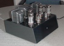
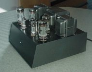
Pictures will follow tomorrow. I used a standard-issue 2-piece metal chassis as foundation, but the color scheme and tube layout make it look rather striking for such a plain beast.
Since I do have source followers between the input differential stage and the output stage, I really don't need to be running the input JFETs hot and heavy at 5mA apiece. If I reduce the JFET currents to 2mA/side and use 100K load resistors instead of 39k, I'll keep a good portion of the input stage gain, but reduce the bandwidth of the differential stage, hopefully to an extent that I won't have to work so hard to suppress spurious oscillation. Anyway, I'll listen to the amp for a while as-is before I make any more changes. It sounds authoritative. I wish I'd had the 30W/channel at Burning Amp this year.
Pictures will follow tomorrow. I used a standard-issue 2-piece metal chassis as foundation, but the color scheme and tube layout make it look rather striking for such a plain beast.
Last edited:
Attached are a couple of rough and ready photos of the Kingfisher. Better will follow as time permits. Amp outer chassis and XFMRs are metallic cast iron gray auto touch-up paint, while the top deck is metallic "dark teal" touch-up paint.(Kragen supplied both). The paint is pretty tough after an hour baking time at 200F.As for tubo glow porno stills, I'll have to wait until I get a digital camera that does time exposure. Right now, I'm using a humble Mavica FD-88, floppies and all
Attachments
Last edited:
It was at one time, though the maker (local) is dufunct. I think LMB/Heeger might offer something similar. I picked it up at a surplus store for a fraction of its list cost. The attractive part is that the pieces are made of much thicker aluminum than your standard-issue Bud box. Even so, I may add some bracing - those transformers are heavy. The chassis started out wwith a blue outer shell with off-white top deck - typical LMB colors for their ready-made chassis.The original paint made a fine foundation for the auto touch-up spray.
I did some more looking around and the closest thing to the chassis I used in current production is a slope front cabinet made by Bud. You really don't want to know what Digi-Key wants for the thing - It'll make you cry.
I had a chance to listen to this thing in the home environment last night, and these are my impressions so far.
1) It's quiet, the lowest background noise of any tube amp I've built so far. The common mode cancellation of the differential and succeeding stages no doubt contributes to this.
2) I get a sense of effortless power, more so than a solid state amp of equal or greater power (It's sitting on top of one).
3) The amp handles niceties of tone very well, but is equally at home with something like rock music. It also doesn't suffer by being played loud. Usually I suffer listener fatigue if I turn the music up high - not so with this beast.
All of this is encouraging. This is my first P-P amp, and I begin to see why SY likes them so much.
For Spread Spectrum - As far as blue glow is concerned, the 7591As in the Kingfisher have a discreet little splotch or two of blueness just visible in a dim room -nothing like the 1625s in my "Shrine" amp, which pretty much have blueness all over the envelope. Well, the blue glow is just the cherry on top, and the Kingfisher as it stands is a big sundae all by its lonesome....
So they have less blue than the picture I posted? (mine are EH tubes as well)
Granted, mine don't glow as bright as the picture shows. It was like a 5-second exposure so the glow comes out nice and bright. The glow is pretty even around all of the openings in the plate structure, though and is still visible in a brightly lit room.
Looks like a pretty neat amp you've made. I've been getting excited about fixing mine.
I'm currently enjoying the amp in my living room. When I can nerve myself to do so, I'll haul it back down to the basement and try toning down the input stage bias current on one side to see if I can keep that nice authoritative sound and ditch the tendency for the input stage to oscillate, without having to come down hard and heavy compensation-wise.
When everything settles down again, I'll post a revised schematic.
When everything settles down again, I'll post a revised schematic.
- Status
- Not open for further replies.
- Home
- Amplifiers
- Tubes / Valves
- "Kingfisher" P-P Amp using 7591A Outputs and Fisher 500B Iron