M. V. Kiebert of Indianapolis Indiana
Not a name you here all the time.
https://www.pearl-hifi.com/06_Lit_Archive/02_PEARL_Arch/Vol_01/Sec_01/065_Dsgn_Fctrs_for_PwrAmps.pdf
In Particular is the very last amp on the page.
Designed for the BBC no less.
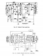
It's a 100 watt continuous amplifier using a quad of 300Bs
Into a FREED 18777 output transformer.
Sadly there are NO component figures given in Mr Kieberts schematic.
Now here's the part that gets me.
How can you get a 100 watts out of a quad of 300Bs?
In the paragraphs above the schematic he references a 200 watt short burst peak power.
I found this site after reading what our friend Lillenthal wrote about Kiebert here:
100 Amplifiers, part 2 , 1945 – 54 | Lilienthal Engineering
100 Amplifiers, part 2 , 1945 – 54 | Lilienthal Engineering
I'll paste his write up below,
Kiebert’s 45 W Williamson, 1954,
Very cool designer – top class circuits – one of the few at my top 5 list. Yet , Kiebert is as good as unknown in the DIY community as well as elsewhere…..This is sad in my opinion, because Kiebert was so much ahead of the others at the time and still to this day his circuits are way better than the 99%. I wonder why nobody discusses his circuits and why no one has copied or learned from these master class designs…?
Anyway – Kiebert was a hardcore Williamson fan. He did not use any of the values from the original circuit – he hardly used anything at all, except the circuit blocks. Kiebert was fast to spot the weaknesses in the components and feedback scheme of the Williamson, but also to recognise that the circuit itself was close to ideal. . When we look at the circuits of Kiebert we can actually sense that these are circuits of high technical insight and that they are very carefully designed. Nothing is random or made from what was at hand. Starting at the input, Kiebert uses a 100 k Ohm pot ! ..Now this is in the mid 1950’s and some 30-40 years ahead in time. So much better that the usual 0.5 to 1 M or more, that was common way up to relative recent.. Then he uses the 12AY7 instead of the usual 12AX7. This alone improves all merits of the amplifier, from noise to freq response. Then a 5687 as driver, which provides a lot of headroom, in fact oceans of such compared to 12AX7, 12AT7, 6SN7 etc. This is indeed very clever and again way ahead from the usual at that time, even compared to 90% of today’s driver topology. Kiebert always used 12AY7 as input and phase splitter, followed by a 5687 as the driver. This is a combination that I have learned to value and used from time to time myself. But Kiebert does not stop there. He really wants the power and juice out of that driver – hence the cathode follower…..same headroom 5687. And why not avoid the AC coupling, drive directly and bias at the same time…. [IMG]
Kiebert continues the tour de force and wants to hold that cathode follower tight by Voltage regulation from a 12BH7. Do also note the clever filament scheme, the use of swinging choke input, and two parallel 5V4/GZ34 for best possible regulation and soft start to prolong tube life. I wonder why he used the filter constants to bypass the plate resistor at the input and to the grids of the 5687. I am also a little puzzled by the 82 Ohm resistor at sg2 of the 807’s. Why not a 100 Ohm ? But then with Kiebert I just know there is a good reason and I won’t question this. I am amused by the weird way Kiebert draws his circuits. Don’t you just love these miles long resistors ? I have redrawn the circuit a little as it was kind of a mess….I spotted an error in the circuit while doing so, that I felt was amusing, hence I left it there….. Do you see it ?
I will give you a hint….Look at the PSU…..
Yup , Kiebert uses solid state to supply the negative bias. That is good engineering too….Have you found the mistake….?……These two solid state diodes are turned 180 degrees….The negative side faces to the AC instead of the bias…. He he…..
Sadly this model is a class B design, however all we need to do is to adjust it in to the class A area and we are all flying.
Apparently Kiebert fancied the 807’s as most of the designs I know from his hand uses these. He did make a 70 Watt 6146 PP and a 100 Watt 4 x 300B PP for BBC.
Kiebert took a few cool audio power amp patents in 1959 as well.
Kiebert you were a sleeper’t, but now you are a keeber’t……I hope that I have hereby printed your name into the history of audio technology.
Hats off to Kiebert.
Not a name you here all the time.
https://www.pearl-hifi.com/06_Lit_Archive/02_PEARL_Arch/Vol_01/Sec_01/065_Dsgn_Fctrs_for_PwrAmps.pdf
In Particular is the very last amp on the page.
Designed for the BBC no less.
It's a 100 watt continuous amplifier using a quad of 300Bs
Into a FREED 18777 output transformer.
Sadly there are NO component figures given in Mr Kieberts schematic.
Now here's the part that gets me.
How can you get a 100 watts out of a quad of 300Bs?
In the paragraphs above the schematic he references a 200 watt short burst peak power.
I found this site after reading what our friend Lillenthal wrote about Kiebert here:
100 Amplifiers, part 2 , 1945 – 54 | Lilienthal Engineering
100 Amplifiers, part 2 , 1945 – 54 | Lilienthal Engineering
I'll paste his write up below,
Kiebert’s 45 W Williamson, 1954,
Very cool designer – top class circuits – one of the few at my top 5 list. Yet , Kiebert is as good as unknown in the DIY community as well as elsewhere…..This is sad in my opinion, because Kiebert was so much ahead of the others at the time and still to this day his circuits are way better than the 99%. I wonder why nobody discusses his circuits and why no one has copied or learned from these master class designs…?
Anyway – Kiebert was a hardcore Williamson fan. He did not use any of the values from the original circuit – he hardly used anything at all, except the circuit blocks. Kiebert was fast to spot the weaknesses in the components and feedback scheme of the Williamson, but also to recognise that the circuit itself was close to ideal. . When we look at the circuits of Kiebert we can actually sense that these are circuits of high technical insight and that they are very carefully designed. Nothing is random or made from what was at hand. Starting at the input, Kiebert uses a 100 k Ohm pot ! ..Now this is in the mid 1950’s and some 30-40 years ahead in time. So much better that the usual 0.5 to 1 M or more, that was common way up to relative recent.. Then he uses the 12AY7 instead of the usual 12AX7. This alone improves all merits of the amplifier, from noise to freq response. Then a 5687 as driver, which provides a lot of headroom, in fact oceans of such compared to 12AX7, 12AT7, 6SN7 etc. This is indeed very clever and again way ahead from the usual at that time, even compared to 90% of today’s driver topology. Kiebert always used 12AY7 as input and phase splitter, followed by a 5687 as the driver. This is a combination that I have learned to value and used from time to time myself. But Kiebert does not stop there. He really wants the power and juice out of that driver – hence the cathode follower…..same headroom 5687. And why not avoid the AC coupling, drive directly and bias at the same time…. [IMG]
Kiebert continues the tour de force and wants to hold that cathode follower tight by Voltage regulation from a 12BH7. Do also note the clever filament scheme, the use of swinging choke input, and two parallel 5V4/GZ34 for best possible regulation and soft start to prolong tube life. I wonder why he used the filter constants to bypass the plate resistor at the input and to the grids of the 5687. I am also a little puzzled by the 82 Ohm resistor at sg2 of the 807’s. Why not a 100 Ohm ? But then with Kiebert I just know there is a good reason and I won’t question this. I am amused by the weird way Kiebert draws his circuits. Don’t you just love these miles long resistors ? I have redrawn the circuit a little as it was kind of a mess….I spotted an error in the circuit while doing so, that I felt was amusing, hence I left it there….. Do you see it ?
I will give you a hint….Look at the PSU…..
Yup , Kiebert uses solid state to supply the negative bias. That is good engineering too….Have you found the mistake….?……These two solid state diodes are turned 180 degrees….The negative side faces to the AC instead of the bias…. He he…..
Sadly this model is a class B design, however all we need to do is to adjust it in to the class A area and we are all flying.
Apparently Kiebert fancied the 807’s as most of the designs I know from his hand uses these. He did make a 70 Watt 6146 PP and a 100 Watt 4 x 300B PP for BBC.
Kiebert took a few cool audio power amp patents in 1959 as well.
Kiebert you were a sleeper’t, but now you are a keeber’t……I hope that I have hereby printed your name into the history of audio technology.
Hats off to Kiebert.
Attachments
Also I will say for the record that Kiebert Schematics are hard as hell to read.
Get your good spectacles out!
Get your good spectacles out!
Attachments
I found a HIGH detail of this circuit. Kieberts article starts on page 166.
Page 171 is the 100 watt amplifier. He writes about it in detail. So NO I don't believe it's a misprint.
https://www.americanradiohistory.com/Archive-Electronics/50s/Electronics-1955-04.pdf
Figure 17 says "Primary of output is a total of 1650 ohms" And the secondary shows 16 ohms.
Now I know of some UTC transformers that have a 2500 & 1500 Ohm plate to plate primaries. But these are rated for 40 watts.
The FREED 18777 must be a beast.
Total trivia here. His full name was Martin Peter Vlamingh Kiebert Jr
Found it on ancestory.com
IEEE Xplore Full-Text PDF:
Found it on ancestory.com
IEEE Xplore Full-Text PDF:
Last edited:
I downloaded the files above to my pintrist account. I'm going to leave links below.
Just FYI guys. Apologies if you're not signed up for that site.
https://i.pinimg.com/originals/11/81/7e/11817e9d40b96e67f324ca7267950eb2.jpg
https://i.pinimg.com/originals/2a/8e/c3/2a8ec3f245d85dd87683405743318f76.jpg
https://i.pinimg.com/originals/98/5c/63/985c637b92b3c20a17aded1597d3761c.jpg
https://i.pinimg.com/originals/85/3e/07/853e07d08bf007214ca6f899dd498802.jpg
https://i.pinimg.com/originals/8b/1e/00/8b1e00728ef12eb4be4d8b8aa7b075d2.jpg
Hi, I am almost certainly kicking a dead horse but I also stumbled upon the glowing review of this Kiebert circuit on "100 amplifiers". I have most of the tubes on hand so I am curious... did you pursue this and further?
That is one of the most intriguing elements and I am also compelled to try that version of the circuit (I have the Bh7 tubes already)... at the same time, I really don't need a 45W amplifier. Its a lot to take one and I would feel much more comfortable investing the time and money necessary if I knew that someone had successfully executed this schematic and might be willing to offer a little guidance.
In my opinion, this is a very complex amplifier to build. The power supply is complicated by the choke-input design. You need a true swinging choke, not as standard choke, and those are hard to come by these days. You could change it to a cap-input supply, but that involves determining the target B+ voltage, which is probably around 400VDC. The negative supply is tricky as well, coming right off the main HV taps.
More critically, we have no idea what output transformer was intended, at least I cannot tell. Without that information, you'll have to experiment with the amount of negative feedback (which is also not certain--20dB?). What plate-to-plate load did he use to achieve 45 wpc? Perhaps 3K, or 6.6k? I don't know. Also, since this is a Williamson design, stability is going to be a factor, and the output transformer has to be very, very good to handle the feedback without oscillating.
I'm a fairly experienced builder but this would be a real challenge for me.
I *have* built Kiebert's 24wpc Williamson. It was pretty zippy, with high input sensitivity. I frankly prefer the more relaxed sound of the original 6SN7 tubes and don't find find the original as problematic as Kiebert makes it out to be. But in terms of bandwidth and transient response, Kiebert's version excels the original.
If you don't need 45wpc, but want to try a Kiebert design, I would suggest the 11 or 24 wpc versions in the original article. Here he uses the Peerless S-265-Q, a magnificent transformer. Heyboer makes a *very* good copy, for about $225 each. They work every bit as well as the original in American Williamson designs. In this way you are not flying blind, the design is much simpler, and the sound is quite excellent.
Here's version of the original paper that is easiest to read, I think.
http://www.one-electron.com/Archive...System Design Factors for Audio Ampifiers.pdf
I have to think that a lot of Kiebert's design were thought exercises. I wonder how many amateurs actually built the more complicated ones...
Thanks for the input and for the document. That is a very helpful version of the schematics, as it details the power supplies for the 11 and 24 watt versions.
One of those is definitely a more reasonable project to consider.
I am often drawn to exotic circuits (and tubes) but I am an intermediate amp builder at best, so it would be irresponsible of me to try to build a circuit as complex as the 45 watt Kiebert.
I may try the 11 watt version and I will post about it somewhere on the forum if I do.
I understand completely. 🙂 The Kiebert Williamson mods are interesting. But IMHO, if you want to build a really wonderful, musical amplifier, purchase a pair of the Heyboer S-265-Q copies and build a "Gilded Lily," the famous version of the ultralinear Williamson suggested by Sarser and Sprinkle. I wouldn't replace mine for anything.
Attachments
Thanks for the suggestions and for the annotated schematic. I think I'll start keeping an eye out for the parts for this instead of pursuing the Kiebert versions ( maybe someday I'll come back to them).
I'll probably have some questions for you, but since its not on topic for this thread, I'll either message you directly or start a new one.
I'll probably have some questions for you, but since its not on topic for this thread, I'll either message you directly or start a new one.
Feel free to. The schematic is of a Heathkit W2, modified to more closely track the original "Musician's Amplifier" it was based on. That was the first American Williamson. Heathkit used a smaller Peerless output (though it's very nice one). I 'scoped all the output options for best response and good stability. Suggest Hammond 274BX PT and 193D choke, with 5V4 rectifier. Gives you that sweet original sound. A 10uF film cap after the rectifier is a nice touch, and Kemet makes 600VDC snap-in caps which save a lot of space. Using the 50% taps on the Heyboer/Hammond (and be sure you specify that if you order them) gives it a more triode-like sound. Very rich, realistic presentation.
- Home
- Amplifiers
- Tubes / Valves
- Kiebert Amplifiers