R117 looks to be burnt or taken heat at one time.
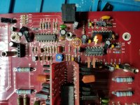
The attachment shows testpoints for the Class D circuit.
Brown arrows- Test points for the drive waveforms. Again you should see waveforms similar to the drive waveforms in power supply.
Yellow Lighting Bolt- This will be a triangle waveform. Without it the LM361 comparator has no reference and will not produce drive waveforms.
Yellow circle- R117- This may indicate why the class D may not be working. I need to check schematics to see what it is tied too.
Again I know this is a lot, but the more I'm able to see what the test points look like, the better I'm able to point you in the right direction
Attachments
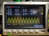
+/-12 on preamp board present. So is the 40hrtz sinwave.
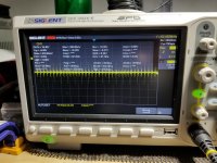
I can't get the scope to view any drive signals at the gates without signal.
I can't get the scope to view any drive signals at the gates without signal.
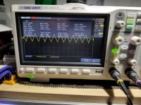
This is at the out pin of the preamp board. I been trying to find a drive signal. I had a very small sqaurewave before I installed the output transistors. Only signal I can see is faint on the n channel transistors gates with the signal.
Attachments
Okay, Look at the test points on the Class D circuit and measure the DC voltages around the LM361 and U102, and post as follows:
LM361
Pin 1
Pin 2
Pin 3
Pin 4
Pin 5
etc...
U102
Pin 1
Pin 2
Pin 3
etc...
The screenshot you just posted is what I would expect. I leaning toward an issue with the Class D circuit. It's possible the LM361 and or U102 is not getting its operating voltages.R117?
LM361
Pin 1
Pin 2
Pin 3
Pin 4
Pin 5
etc...
U102
Pin 1
Pin 2
Pin 3
etc...
The screenshot you just posted is what I would expect. I leaning toward an issue with the Class D circuit. It's possible the LM361 and or U102 is not getting its operating voltages.R117?
Lm316
1: 5.26vdc
2: .002vdc
3: -7.00vdc
4: -6.34vdc
5: .005
6: -18.66
7: .005
8: -3.32
9: -3.33
10: -8.91
11: -3.32
12: .003
13: -3.42
14: -3.44
1: 5.26vdc
2: .002vdc
3: -7.00vdc
4: -6.34vdc
5: .005
6: -18.66
7: .005
8: -3.32
9: -3.33
10: -8.91
11: -3.32
12: .003
13: -3.42
14: -3.44
And the u102:
1: -.801vdc
2: -.704
3: -.703
4: -.704
5: -.689
6: -.701
7: -.623
8: -6.51vdc
9: -1.089
10: -.268
11: -.089
12: -6.45
13: -.568
14: -.567
15: -6.73
16: 5.236vdc
1: -.801vdc
2: -.704
3: -.703
4: -.704
5: -.689
6: -.701
7: -.623
8: -6.51vdc
9: -1.089
10: -.268
11: -.089
12: -6.45
13: -.568
14: -.567
15: -6.73
16: 5.236vdc
Okay, I see a problem, Pin 1 should be +12v not +5.26. Pin 6 should be -12v not -18v. There is localized 6 volts bucking the +/-12 volts. This may have something to do with R117. I will need to look at my schematics. Go ahead and check R117 with an ohmmeter. Also, post DC voltages around U102 and U105. I will post again tommorow morning if I can.
It just occurred to me the reference you used to make DC voltage measurement may be wrong.The Black probe of meter should be to the power transformers secondary center tap. If you used the power ground terminal that would explain the 6 volt differential. Apologizes for not making that clear.
In either case the fact that you have a triangle wave and no drive waveform tells me the LM361 is failing or not getting the right operating voltages.
In either case the fact that you have a triangle wave and no drive waveform tells me the LM361 is failing or not getting the right operating voltages.
FYI the drive pins on U101-LM361 are Pins 9 & 11 as I original stated.
Looking at your data, it appears that LM361 has failed and may be why R117-22 ohm resistor burned up. R117 is tied to Pin 6 of the LM361 and -12 volts. And Pin 8,10,13,14 appear to be shorted together.
Once you have an opportunity, recheck your measurements using the Transformers secondary center tap.
Ok so the new lm361N arrived today. Installed it. The amplifier will not start, just clicks the relay over and over. Just like the in protection thing.
Did you change out R117? Is it possible an output shorted?
I will look for a way to disable protection tomorrow.
I will look for a way to disable protection tomorrow.
yes 22 ohms. They are all new, and i dont read any shorts. I'll recheck, would a faulty driver card cause this as well?
Remove one driver board at a time.If removing a board brings the amp out of protection, check the opposite side for drive at the output gates with your scope. Post screen shots.
If you determine that one board is good, install the board on the opposite side and check for drive at the gates. again post screen shots.
If you are able to get amp out of protection removing one or both boards, check
the DC voltages(Pins 1-14) and waveforms (Pins 4,9,11) on the LM361 as you did before. Post your measurements and screen shots.
There is an R21-4.7Kohm resistor an the Sub 3 daughter board in the power supply.Removing it should disable all protections. If you do this be very careful when turning amp on and monitor current and temperature if possible. Maybe last resort.
- Status
- Not open for further replies.
- Home
- General Interest
- Car Audio
- Kicker zx2500.1 power issues