Oh. Timebase was actually set to full CCW. Multiplier was at 1x. I think I set the timebase to that so that I could view in on <100hz frequencies without having the screen flicker so much but I dont think it helped any. Timebase is set to cal now.
I got differential mode to work. Shows about a 9v square wave on screen probing Source and Gate. I previously found similar square wave when setting one probe to AC coupling on gate. The differential way DC coupled shows the square wave's bottom on the X-axis.
I got differential mode to work. Shows about a 9v square wave on screen probing Source and Gate. I previously found similar square wave when setting one probe to AC coupling on gate. The differential way DC coupled shows the square wave's bottom on the X-axis.
Both channels need to be set to DC coupling.
In AC mode, you can't tell if the waveform is driving back to ground.
In differential mode, you can get high resolution waveforms even if they have significant DC offset.
Are both the high and low-side waveforms driving back to the reference line?
In AC mode, you can't tell if the waveform is driving back to ground.
In differential mode, you can get high resolution waveforms even if they have significant DC offset.
Are both the high and low-side waveforms driving back to the reference line?
Im going to say YES to that question, but I dont trust differential mode on this scope as I do not think Invert button is working correctly. When I press Invert even with the probes disconnected from the scope the trace line jumps off axis by about 3/4". Everything else seems calibrated when not activating invert.
I can see the 10v square wave on the gate pads both high and low sides.
High side doesn't need differential mode to observe the 0-10v square wave as source is 0vDC which is the same as amp's ground and amp's positive speaker terminal.
Low side, I see a 10v square wave on AC coupling, but in differential mode its off the X-axis I believe on account of my invert feature not working correctly on channel 1. Using my DVM, I get 4.5v on gate pad referencing source pad and so I can probably determine the waveform is falling back to reference on account of that reading.
Reading through the documentation on BK 2120, only Channel 1 can be inverted. CH2 trace is not affected by invert nor has an invert function.
When I have time I'm going to look through the schematics on this scope and see if something is wrong with invert circuits.
When I have time I'm going to look through the schematics on this scope and see if something is wrong with invert circuits.
For ch2 in normal mode, touch it to 12v. It should deflect up. Now switch to invert. It should deflect down the same distance as it did up.
12v attached to both probes. ch1 probe ground to negative. Both probes at 1x.
INV1 button only inverts ch1.
There seems to be no INV2 feature on this scope.
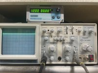
5V/Div.
1. First photo with 1 line, is actually traces from BOTH channels at the same point at +12v.
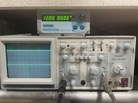
2. Second photo shows CH1 inverted with INV1 pressed. You can see the invert function is not operating correctly as the trace for CH1 is only at -6 where it should be at -12.
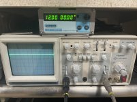
3. third photo is the differential reading. This should have been 0v but since CH1 in not inverted correctly its showing +6v
INV1 button only inverts ch1.
There seems to be no INV2 feature on this scope.
5V/Div.
1. First photo with 1 line, is actually traces from BOTH channels at the same point at +12v.
2. Second photo shows CH1 inverted with INV1 pressed. You can see the invert function is not operating correctly as the trace for CH1 is only at -6 where it should be at -12.
3. third photo is the differential reading. This should have been 0v but since CH1 in not inverted correctly its showing +6v
Attachments
Last edited:
Can I safely put output FETs back in circuit with pin 6&7 jumped? I wonder if the feedback circuit is working correctly.
U201 WITH 6&7 jumped on U200
1. 15.2
2. 0.019
3. 0.019
4. 0.019
5. -15.4
6. 0.020
7. 0.020
8. 0.080 <-- Flat. No triangular signal
U201 with U200 6&7 NOT jumped
1. 15.4
2. 0.018
3. 0.018
4. 0.018
5. -15.4
6. -0.354
7. -0.354
8. -3.925 <-- Flat. No triangular signal
1. 15.2
2. 0.019
3. 0.019
4. 0.019
5. -15.4
6. 0.020
7. 0.020
8. 0.080 <-- Flat. No triangular signal
U201 with U200 6&7 NOT jumped
1. 15.4
2. 0.018
3. 0.018
4. 0.018
5. -15.4
6. -0.354
7. -0.354
8. -3.925 <-- Flat. No triangular signal
OK here it is correct. Also 1,2,3 of the second set is actually positive not negative.
U201 WITH 6&7 jumped on U200
1. 0.080 flat
2. 0.020
3. 0.020
4. -15.4
5. 0.02
6. 0.02
7. 0.02
8. 15.2
U201 with U200 6&7 NOT jumped
1. 3.925 flat
2. 0.354
3. 0.354
4. -15.4
5. 0.018
6. 0.018
7. 0.018
8. 15.4
U201 WITH 6&7 jumped on U200
1. 0.080 flat
2. 0.020
3. 0.020
4. -15.4
5. 0.02
6. 0.02
7. 0.02
8. 15.2
U201 with U200 6&7 NOT jumped
1. 3.925 flat
2. 0.354
3. 0.354
4. -15.4
5. 0.018
6. 0.018
7. 0.018
8. 15.4
The reason that pin 6/7 were jumped was to get the drive waveform at the outputs without the ground jumper. Do you still have drive at the outputs?
That's because the feedback loop is open. If you jump 6/7 and drive a signal into the amp, do you get modulation of the drive signal?
Yes I can see modulation on drive signal with 6/7 jumped.
Still though with output FETs in circuit R134 goes up. I wonder if these FETs are failing. They're measuring OK off the board. IXTQ36N30P.
Drive circuit under load problem?
Still though with output FETs in circuit R134 goes up. I wonder if these FETs are failing. They're measuring OK off the board. IXTQ36N30P.
Drive circuit under load problem?
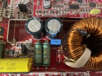
C108 the cap marked 105 is in series with R134. The two components are essentially connected to the positive and negative speaker terminals.
The blue cap is not an original. Amp came in with R134 and C108 destroyed.
The blue cap is not an original. Amp came in with R134 and C108 destroyed.
The 1200 diagram shows that cap as a 1000pf (marked 102). They are R316 and C305 on the diagram. Is that what you have?
- Home
- General Interest
- Car Audio
- Kicker ZX1500.1