So all my voltages are present from the main board.The audio signal is getting to the class d board What else could be wrong with the class d board if that capacitor was blown to be removed in the first place? I have +-15vdc and 5vdc, if I probe the pin labeled drive on the class d board what should be there?
Last edited:
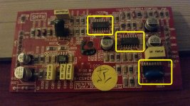
The attachment shows the three IC's to focus on.
Check the DC Voltages on U202, U203 and U204.
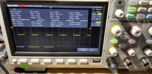
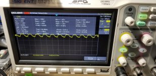
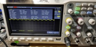
With a scope check around U203. If the IC is functioning you will see rectangular waveforms on multiple pins. Pin 1, I believe is the output.
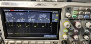
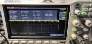
On U202 check the waveforms of Pin 3(audio input), Pin 4(Triangle Wave), Pins 9 & 11-(Rectangular waveforms).
U204 is the output drive(rectangular waveforms) which aren't present. Its possible that this IC has failed, but more than likely U202 or U203 has failed.
Once you've posted the DC voltages and waveforms (Just post the screenshots of the U202 for now) It will help to diagnose the issue and help to determine what direction to go in.
Check the DC Voltages on U202, U203 and U204.
With a scope check around U203. If the IC is functioning you will see rectangular waveforms on multiple pins. Pin 1, I believe is the output.
On U202 check the waveforms of Pin 3(audio input), Pin 4(Triangle Wave), Pins 9 & 11-(Rectangular waveforms).
U204 is the output drive(rectangular waveforms) which aren't present. Its possible that this IC has failed, but more than likely U202 or U203 has failed.
Once you've posted the DC voltages and waveforms (Just post the screenshots of the U202 for now) It will help to diagnose the issue and help to determine what direction to go in.
Attachments
So all my voltages are present from the main board.The audio signal is getting to the class d board What else could be wrong with the class d board if that capacitor was blown to be removed in the first place? I have +-15vdc and 5vdc, if I probe the pin labeled drive on the class d board what should be there?
You should have Rectangular waveforms on the drive pins.
U202 ------------------------- U204
1.) 15.01 -------------------------1.) .001
2.) .005 ==============2.) .002
3.) -1.081 ==============3.) .009
4.) .091v --------------------------4.) 3.195
5.) .002 -------------------------5.) 2.488
6.) -15.02 -------------------------6.) -15.56
7.) .002 -------------------------7.) 4.968
8.) 1.394 -------------------------8.) .008
9.) 4.94 -------------------------9.) -15.56
10.) .008 -------------------------10.) 4.551
11.) 2.058 -------------------------11.) 15.36
12.) .000 -------------------------12.) 2.490
13.) 1.395 -------------------------13.) 4.957
14.) 4.961 -------------------------14.) .000
Last edited:
There should near zero volts on the audio input, Pin 3 of U202 and Pin 4 should be a triangle wave. Follow the waveform from Pin 5 of U203 to Pin 2 of U200 then Pin 1 of U200, then the other side of C230 and post screen shots.
Check the DC voltages around U200 and U201 and post. The -1 volt on Pin 3 of U202 suggests that something in the feedback loop has failed, which U200 and U201 are in the loop.Or there may be a problem with one or both of the output mosfet drive circuits which are on the main board near the outputs.
Check the DC voltages around U200 and U201 and post. The -1 volt on Pin 3 of U202 suggests that something in the feedback loop has failed, which U200 and U201 are in the loop.Or there may be a problem with one or both of the output mosfet drive circuits which are on the main board near the outputs.
Pin 3 of u202 has -1.036vdc on it, I just double checked it. I am running a 40hrtz 5v signal into the amplifier. Voltages are as follows:
U200
1.) -14.78
2.) -14.80
3.) -13.86
4.) -15.53
5.) -13.48
6.) -15.39
7.) -1.069
8.) 15.36vdc
U201
1) -5.456
2) -.555
3) -.556
4) -15.53
5) .004
6) .003
7) .003
8) 15.32vdc
U200
1.) -14.78
2.) -14.80
3.) -13.86
4.) -15.53
5.) -13.48
6.) -15.39
7.) -1.069
8.) 15.36vdc
U201
1) -5.456
2) -.555
3) -.556
4) -15.53
5) .004
6) .003
7) .003
8) 15.32vdc
Try replacing U200-OP275 and U202-LM361. The Mouser links below are a good source for the chips.
OP275GSZ-REEL Analog Devices | Mouser
LM361MX/NOPB Texas Instruments | Mouser
OP275GSZ-REEL Analog Devices | Mouser
LM361MX/NOPB Texas Instruments | Mouser
- Status
- This old topic is closed. If you want to reopen this topic, contact a moderator using the "Report Post" button.
- Home
- General Interest
- Car Audio
- Kicker zx1000.1 input board help