As Perry said,at this point without the FET's in place you will only see drive at the gate. You might try swapping the boards from one side to the other to see if the lack of drive follows the driver board.
If you determine a driver board is bad, use a spare board from the other 2500.1 and leave the good board in.
If you determine a driver board is bad, use a spare board from the other 2500.1 and leave the good board in.
Both sides had a perfect drive signal, all four banks. I just noticed that the other two were different on the one bank (but as Perry pointed out, that's basically just meaningless static -- I didn't even consider that.) Will I be able to try it with only the 9640's or is it a bad idea to only install the 20 9640's and not the 12 FB31? I only have 3 left that I did not damage. Or, am I able to install only 5 or 10 of the 9640's at a time and try it (to see if the waveform is proper)? I'd love to if possible take less risk and install and uninstall transistors as little as possible, plus keep diagnostic steps small so it is easier to troubleshoot if something does go wrong.
Personally, I wouldn't install the FETs for only one rail. In some amps, having unequal drive to the inductors can cause excessive rail voltage to build and blow the rail caps. You can insert a small capacitor (0.01uf or something close connected across pads 1 and 3) to load one FET location to see if the square wave drive remains OK.
If you had all of the FETs, you could remove the rectifiers to see if the drive remained OK.
If you had all of the FETs, you could remove the rectifiers to see if the drive remained OK.
If you have some IRF640's they can be used for testing. Loading one 640 in each of the four FB31 banks and one 9640's in their respective banks should be sufficient for testing.
Sent from my HTC Desire 626 using Tapatalk
Sent from my HTC Desire 626 using Tapatalk
Okay, I tested with 640's. Here are my findings.
-1 IRF640, 1 IRF9640 (verified working with my DCA55) per bank.
Test 1:
-All Banks Loaded
-All Driver Cards Installed
Result: Repeated cycling through protect/on
Test 2:
-All Banks Loaded
-Only Banks 3/4 Have Driver Card
Result: Power on. Idle at ~1.3A
Test 3:
-All Banks Loaded
-Removed Known Good Driver Card From Banks 3/4, installed in 1/2
Result: Repeated Protect Cycling
Test 4:
-Removed IRF640 from Bank 2 (probably was not wise, meant to remove both)
-Driver Card Still In
Result: Slightly faster protect cycling
Test 5:
-Removed both FETs from Bank 2 (Bank 1 still fully loaded)
-Driver Card Still In Banks 1&2
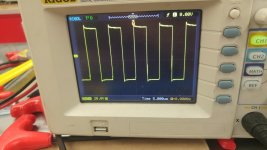
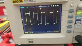
Result: Power On. Idle at ~1.3A. Tested waveforms on this, two pins have nice 'relatively' square wave.
So I'm going to have to say it's almost definitely something with bank 2, and not on the driver card, causing the issue. Any suggestions from here? One more thing to note, I have been using a 10A fuse this whole test and it did not blow it when cycling. Not sure if that's relevant or not, but yes.
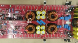
Photos included are of the two of three pins that had a square wave on them of the FETs, and the board I am working on and how I labelled it (please disregard my slight searing of the board near the driver cards, and the flux everywhere).
-1 IRF640, 1 IRF9640 (verified working with my DCA55) per bank.
Test 1:
-All Banks Loaded
-All Driver Cards Installed
Result: Repeated cycling through protect/on
Test 2:
-All Banks Loaded
-Only Banks 3/4 Have Driver Card
Result: Power on. Idle at ~1.3A
Test 3:
-All Banks Loaded
-Removed Known Good Driver Card From Banks 3/4, installed in 1/2
Result: Repeated Protect Cycling
Test 4:
-Removed IRF640 from Bank 2 (probably was not wise, meant to remove both)
-Driver Card Still In
Result: Slightly faster protect cycling
Test 5:
-Removed both FETs from Bank 2 (Bank 1 still fully loaded)
-Driver Card Still In Banks 1&2
Result: Power On. Idle at ~1.3A. Tested waveforms on this, two pins have nice 'relatively' square wave.
So I'm going to have to say it's almost definitely something with bank 2, and not on the driver card, causing the issue. Any suggestions from here? One more thing to note, I have been using a 10A fuse this whole test and it did not blow it when cycling. Not sure if that's relevant or not, but yes.
Photos included are of the two of three pins that had a square wave on them of the FETs, and the board I am working on and how I labelled it (please disregard my slight searing of the board near the driver cards, and the flux everywhere).
Attachments

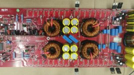
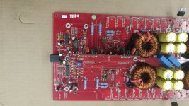
L201 may have shorted windings-remove the inductor and reload output devices and retest. Removing L201 will allow the amp to power up normally and produce output assuming the inductor is the issue causing the amp to self protect and damage the output devices.
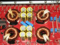
The image I reposted appears to show delaminated windings inside the white circle.
The image I reposted appears to show delaminated windings inside the white circle.
Attachments
Last edited:
Funny, I was just re-reading the "Generic Class D 1" page that showed this is a possibility. I'll try pulling it tomorrow night. If it does function I'll try replacing it with one of the other 4 from the spare amp.
I would recommend adding sleeves to the leads of all output Inductors. The red sleeving was not adequate and quite often became perforated due to heat and friction,which may be the case here. I will send pics of the tubing which is a coated white woven fiber.
Sent from my HTC Desire 626 using Tapatalk
Sent from my HTC Desire 626 using Tapatalk
It's probably silicone coated fiberglass tubing. Correct me if that's incorrect:
https://www.techflex.com/prod_sg.asp
See attached.
https://www.techflex.com/prod_sg.asp
See attached.
Attachments
Here is the spec sheet for the sleeving in your photo, Perry. Its a fiber glass coating. AG155-C1 to be specific. I'm imagine the techflex tubing would work as well.
Attachments
Last edited:
Okay, excellent! I removed the inductor and it did indeed allow the amp to fire up and produce audio, drawing ~4.5A at idle. Does that mean it is 'pretty likely' to be the issue, or could there be parts after this inductor down the line, so to speak, causing the protect issue? Just figured I'd see if there is anything else I should check before I slap a replacement inductor on it and give it a test.
I'll definitely give it a go with the tubing, if that'd make it more reliable, once I've got it confirmed up and running.
What should I use for fixative? I dug through the repair tutorial, and found the adhesives chart. It's seeming like silicone would be the proper choice, yes? I'm not positive what would be wise to use, but I'm thinking the Silicone II caulk (without acid content) might not be such a bad choice. Please do correct me if wrong or there is a better option. What is that black goo that's currently there?
Thank you again for all your help so far, I will post further results when I can get the other inductor slapped in.
Last edited:
In my experience it's the Inductor,other then additional filtering and a relay there is nothing else.
Sleeve if at all possible,both leads.
Silicone caulk is recommended.Not sure what the factory uses for adhesive.
Sent from my HTC Desire 626 using Tapatalk
Sleeve if at all possible,both leads.
Silicone caulk is recommended.Not sure what the factory uses for adhesive.
Sent from my HTC Desire 626 using Tapatalk
Well, we got it. It is fully functional and back in working order. Big thanks to Perry Babin and PapaZBill for all of your assistance; this was one of the worst amp repairs I've had to face so far, and I definitely learned a lot (and have already put what I learned to use on a few other amplifiers). I couldn't have done it without you guys.
One last thing I would like to ask, though -- what purpose 'exactly' does that inductor coil that we replaced serve, and why did it being shorted cause such a huge issue? Good thing to learn, I imagine. Even just a link to somewhere if you have one would be more than appreciated - I couldn't find anything directly relevant to this, or that wasn't above my head.
And, for future people that may stumble across this: I have many pictures I took along the way. If you need something that isn't posted, message me and I'll try to provide it to you or post it here. Remember to check your inductors 🙂
Good to hear, laughatthemall!
Basically, the inductor filters out the digital or PWM component, leaving only the audio. A shorted inductor presents an excessive load to the output mosfets and exceed the current rating of the devices, causing them to burn up and short.
I did a quick google search and find this PDF. I would also recommend Perry Babins web page and tutorial Basic Car Audio Electronics. Especially the tutorial if you are planning on doing more repairs. It is an indispensable resource which I refer to often!
Attachments
I very early on did purchase the tutorial, it has been indispensable for all of the repairs I have done so far. Best 50-ish dollars I've ever spent, for all that I've learned from it. I do know I make quite a few threads, but that is because I want to learn all I can about amplifier repair, instead of turning down repairs that are harder than the typical 'blew some FETs' sort of deal (e.g. referred to as level 2/3 stuff in Perry's tutorial). I'm not as concerned about making sure it is profitable from a time/labor standpoint at this point in time, I am well aware there's quite a steep learning curve, especially in Class D stuff. I'm willing to invest the time, as this is a hobby, not a job, for me - at least at this point I hope some day to be able to help people with their projects as you two did here.
- Status
- Not open for further replies.
- Home
- General Interest
- Car Audio
- Kicker 2500.1 Protect Mode Issues [Repair]