I have a Kicker 2500.1 that I am repairing. The original symptom was blown transistors. I have replaced 20/20 of the IRF3205 power supply transistors, 10/20 of the IRF9640 (one whole side), and 6/12 of the FB31N20D (same side, all on that side). All of the 150-ohm gate resistors on the power supply tested within tolerance. When I attempt to power it with a 15-amp fuse, it pops it. A 20-amp fuse does not pop, only trigger the relay to click and the power LED to flip between 'on' and 'protect' repeatedly. The same thing happens with a 2 ohm limiting resistor placed inline with the power source (albeit the 'click' is much quieter), but does not pop the fuse.
Anyone happen to have any suggestions on where to look next?
Anyone happen to have any suggestions on where to look next?
what equipment are you using? have you checked the voltage, hz, and duty cycle at the power gates? what specific model is it?
D761,762 and D861,862-MUR3040PT can be removed to determine if the problem is in the output or power supply. If after removing them and your able to power up,amp may still be in protection but you can check the drive to the mosfets. With a voltmeter you will see 5 volts to the gates.
The 2005 and 2006 only, used the FB31N20D's,2008 and later used IRF640's.Are there two red colored neoprene gaskets along the length of the amp?this would be a 2006. If not it will have a silver cover plate and a fan, which is a 2005.
The 2005 and 2006 only, used the FB31N20D's,2008 and later used IRF640's.Are there two red colored neoprene gaskets along the length of the amp?this would be a 2006. If not it will have a silver cover plate and a fan, which is a 2005.
Hello again, fello DIY'ers. I lost track of this post -- I didn't realize I had both a DIYAudio AND DIYMA account, looked there, didn't find it, thought I was crazy. Anyhow, here's a bit more insight into my issue. It IS an '06, for the record.
The original issue was the PS was cooked, few outputs damaged. The previous owner admitted to running too low an impedance load. I swapped out the PS FETs, the associated resistors, and changed out the whole PS driver card from an amp whose main board was slightly water damaged. Also replaced the bad output FETs. The FETs also came from the amp. I have an ammeter connected to test input voltage.
When all FETs are in, it appears to damage some of the FB31N20D's, one one side (it uses 20x IRF9640 and 12x FB31N20D's for outputs) and power cycle. By 'damage', I mean it does not short them, but appears to destroy the gate. They definitely heat up quick. I think it's only one of the two 'sets' on that side (groups of 5/3 FETs) that is blowing, I did not check where I removed the blown ones from, stupid me. I have a semiconductor component analyser made by PEAK, for quick/easy testing. A 'good one' reads as an N-channel MOSFET, and a bad one reads as a 'diode or diode junction', identifying the gate as nonexistent, and the other two as cathode/anode.
If I remove the FB31N20D's, the amp powers up fine. If I leave the one side (we'll call it Good Side from here on out) in, but remove Bad Side's FB31's it powers on. It draws about 1.2A when running, with the Bad Side's FB31's out. The power supply seems good. As of now, I've damaged most of my FB31's so I'm metering with none in but all 9640's in. These are the measurements I've taken so far:
Power Supply
4.2v DC
11.8v DC
0.0v DC
NOTE: ALL voltages DC, L to R, facing the part's writing
Group 1/2 - Bad Side
[IRF9640]
46.2v
49.4v
49.2v
[FB31N20D]
-57.8v
48.6v
-62.3v
Group 3/4 - Good Side
[IRF9640]
44.9v
48.8v
48.7v
[FB31N20D]
-58.6v
48.6v
-62.2v
Any idea what I should look at next/what could be causing this? I've looked at both side with a scope and it appears the same between, same with the little 'driver boards' in the middle. Each side appears to be putting out the same voltages/waves.
If anyone has any advice, I'd greatly appreciate it! I will be the first to admit I am not a seasoned professional at repairing amps, but I'm sure trying my best and trying to learn. I have a Rigol DS1102 scope and a decent Extech multimeter, can also use my Fluke clamp meter as a volt-meter/continuity meter if you don't trust the Extech. If any pictures would help provide better answers, I will gladly take them to the best of my ability. Thanks for taking the time to read/reply, guys!
What reference are you using check DC voltages.Use the the secondary center tap of either transformer.
With your scope,check the drive at the gates of each bank of output bank/group and post screen shot.
Sent from my HTC Desire 626 using Tapatalk
With your scope,check the drive at the gates of each bank of output bank/group and post screen shot.
Sent from my HTC Desire 626 using Tapatalk
I have been using B-/power supply ground for ground reference. I will try to get waveforms screenshotted tonight. Thanks!
Here comes a novice question, unfortunately I could not find much info on reliably identifying things, but which would be my center tap here? I don't understand toroidal transformers as much as I should, I will be the first to admit, I have a basic understanding but clearly not as well as I need. For future reference (teach a man to fish, so to speak) is there any way I can reliably identify leads of a transformer, such as to distinguish primary/secondary, or find a center tap? I didn't happen to find any significant resistance differences.
I took some pictures in the event it may help.
Imgur: The most awesome images on the Internet
I took some pictures in the event it may help.
Imgur: The most awesome images on the Internet
For most mono amplifiers that have signal only on the positive speaker terminal, the negative speaker terminal is directly connected to the secondary center tap of the power transformers.
If you look at the secondary as one long winding, the center of that winding is tapped and connected to secondary ground. In most instances, those two center terminals are directly connected by a large trace.
If you look at the secondary as one long winding, the center of that winding is tapped and connected to secondary ground. In most instances, those two center terminals are directly connected by a large trace.
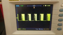
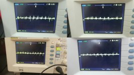
Okay, I got some waveforms. I used the negative speaker terminal for ground, I interpreted Perry's advice to mean that should be a wise choice. I have the amp running on a 15A fuse, drawing ~1A current, the only thing I do not have installed is the tone card (the card that gain/bass boost/xover controls are on) and the FB31N20D's. Remember, banks 1 & 2 are the 'Bad Side', banks 3 & 4 are the 'Good Side' - meaning I can leave the FB31's in without them blowing. Not sure if both banks 1 and 2 are bad or just one or the other - when I pulled the FET's the last time, I had 3 of 6 FB31's blown that were good when in Banks 3 & 4.
Here are the FB31N20D's - FB31N20D - Album on Imgur
Here are the IRF9640's - IRF9640 - Album on Imgur
I hope this is of some help. I do note some discrepancies in pin 2/drain of the transistors. Any idea what this could mean?
Here are the FB31N20D's - FB31N20D - Album on Imgur
Here are the IRF9640's - IRF9640 - Album on Imgur
I hope this is of some help. I do note some discrepancies in pin 2/drain of the transistors. Any idea what this could mean?
It's generally better to post the images on the forum server. If the photos on a different server are deleted, the thread becomes useless for those reading the thread, trying to repair their amp (or simply trying to learn).
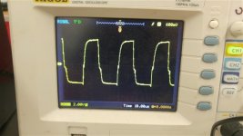
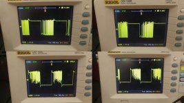
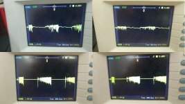
It appears that there is either excessive noise or you scope isn't triggering properly. Did you confirm that the negative speaker terminal read 0 ohms to the secondary center tap?
Can you get a clean waveform image on the power supply FETs?
It also appears that the signal is approximately 1kHz. Is that what you have on the pin of the LM361 (it this amp has that IC)?
Can you get a clean waveform image on the power supply FETs?
It also appears that the signal is approximately 1kHz. Is that what you have on the pin of the LM361 (it this amp has that IC)?
You should see a squarewave w/ a 50% duty cycle much higher than 1khz.This should be 50khz or higher.
Comparing the waveform at the power supply FET's will give you some idea what the output drive should look like as Perry suggests.
The LM361 is underneath the preamp board (you referred to it as a tone card). Using the negative speaker terminal for scope ground, assuming there is zero ohms between neg spkr term and secondary center tap, check and post the waveforms at Pin 4,9 & 11 of the LM361.
I will double check the suggestions you gave me tonight -- I do a good portion of my repairs between 12-8 (I work overnights, but it's a job I literally only have to be alive at. They told me as long as the place does not burn down, I'm welcome to do whatever keeps my eyes open; plus I do all maintenance I can for them.) I could not find the center tap, this is the toroidal transformer I looked for it on. Nothing appeared to show 0 ohms to spk- either.
This is the transformer I have been trying to find the secondary center tap on, no luck on my part.
Imgur: The most awesome images on the Internet
To Perry, how do I upload pictures to the server here? I would absolutely LOVE to put them here for the exact reason you stated, and would even like to have a place to put board pictures I take (for instance, I have a MTX 81000D board I had pulled all of the caps from just to get a clean shot of the board) to share with others.
I'll try to fix my images once I know how, just so they remain there.
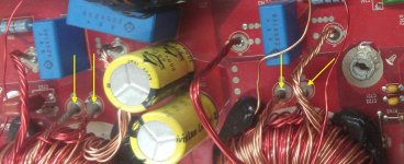
C763 is in line with two leads (one red and one gold) these two leads are the center tap. The other transformer has a blue box cap in line with its center tap. An ohmmeter should see 0 ohms between these two points along with the negative speaker terminal.
If for some reason the neg spkr terminal and center taps are not connected this could cause the noise your seeing on the scope,and an imbalance between the negative and positive rail voltages.Which your DC voltage measurements of the output FETs seem to indicate and should be approximately 60 volts on both the positive and negative side.
Sent from my HTC Desire 626 using Tapatalk
Last edited:
Use the 'go advanced' button and then the 'manage attachments' button to select them from your computer. I don't think you need to do anything with photos that you already posted.
The arrows point to the secondary center taps for each transformer.
The arrows point to the secondary center taps for each transformer.
Attachments
Last edited:
Okay, I have a bit more insight. Neither of those two read zero ohms to the negative speaker terminal. When metering DC voltage using B- terminal as ground, those two posts read -6.52vDC. Between the tap indicated and either speaker terminal (using speaker terminal for negative probe), it indicates about -56vDC (not sure if that actually means anything).
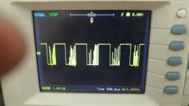
These are the waveforms of the PS FETs using that indicated center tap as ground.
These are the waveforms of the PS FETs using that indicated center tap as ground.
Attachments
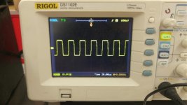

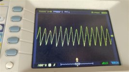
The power supply is referenced to the main ground terminal. That's what you would generally use for the scope ground when checking power supply waveforms.
The reason that I wanted you to check the power supply waveforms was to confirm that you scope was working properly. The waveforms that you were getting for the outputs were not what I'd expect.
As a side note, using DC coupling is important when checking waveforms, especially when checking the gate drive for the power supply (not applicable here but would be if you were troubleshooting the power supply drive circuit).
I don't know if this amp has a bridged output or if one speaker terminal goes to the secondary ground. PapaZBill will know definitively. If it has a bridged output, the negative speaker terminal will not go to the secondary ground (both speaker terminals will have audio). One example here:
http://www.bcae1.com/temp/bp1200p1_sm.pdf
- Status
- Not open for further replies.
- Home
- General Interest
- Car Audio
- Kicker 2500.1 Protect Mode Issues [Repair]