I tried a simple transistor bias analysis after drawing it in KICAD and had problems evidently with nodes not being driven. I verified all connections were made between components. I just added a ground and power.
I remember the pre-GUI SPICE days with having to create netlists and put a resistance in series with voltage sources and in parallel with current sources to prevent errors. It was easier in the sense that you named the nodes on your schematic, so it wasn't too hard analyzing the errors generated...most of the time.
I couldn't figure out what I had to do to 'drive' pins to KICAD's satisfaction.
Short detour - installed LTSpice, drew it with library components and the simulation simply worked.
Any idea if KICAD has quirky requirements for 'simple' elements like DC power and Ground?
Thanks
Last edited:
The ngspice integration is a new feature in KiCad and only in Nightly builds. It may well be buggy
I imagine if you posted a screen-capture image of (a) your schematic; and (b) the error message window that KiCad pops up, then diyAudio members might be able to tell you exactly what has gone wrong. And there's a good chance it isn't your fault, but rather a poorly documented KiCad requirement that's silly and unintuitive, but very easy to remedy quickly. In my opinion!
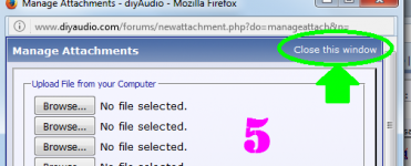
I am not figuring out how to make attachments, or if I can. I see the attach image icon under the "go advanced" expanded menu (after trying the 'basic' icon that acts the same way), but it only offers an external link option. It may just be that way...?
Well, wow, I must be getting old(er).
I've used that attachment method on another site with same forum software...& forgot all about it.
I made a couple changes from my original attempt. I think I started with a DC source then tried a 3-terminal regulator.
LTSpice allowed me to use a 2N4401 device. I'm looking at the DC operating point for a Wenzel DC power supply 'finesse noise filter'. This is the shunt transistor isolated from the rest of the circuit.
I initially did the analysis manually and didn't like the numbers I came up with, so I assumed I forgot something and did it again and get the same results. I think I make the same mistake (assumption) repeatedly.
KICAD is 'biased' toward 'European parts' and closest thing I initially saw to 2N4401 was PN2222A, then I saw BC849 so I put that in today. Nothing to do with my 'grammar errors', but a move toward a similar circuit.
TINA-TI I think a '2222 that gave me different bias numbers but no ERC errors.
LTSpice gave me numbers that agreed with my manual calculations, which didn't care about HFE, so shouldn't matter what transistor is selected.
TINA-TI gave very different numbers, making me think entry error rather than device variation.
If you're familiar with the Wenzel DC supply filter, it basically looks like an AC coupled amplifier that diverts power rail disturbances into a shunt path.
I was curious what it's operating point was as well as its 'limits'...along the thought path of when do you change to a different device.
I found someone who uses the op-amp version (last of 3 topologies proposed by Wenzel), and said its noise-reduction operation is independent of the DC current requirement your circuitry (being fed by the filtered DC supply) needs.
I don't really need to know the bias point anymore, but it sure would be helpful to get expected results I trust so I move onto other challenges. (learning curve).
Thank you
Murray
Attachments
Doggoneit (or whatever)! Only one attachment posted.
Oh, .erc is not a recognized file type.
I got screen shot of schematic fine. ERC would not copy. That makes no sense. Must be my PC acting stupid(er).
----------------------
KICAD .erc contents (same or similar results before using 3-terminal regulator after DC source didn't work).
----------------------
ERC report (2/12/2017 2:36:54 PM, Encoding UTF8 )
***** Sheet /
ErrType(3): Pin connected to some others pins but no pin to drive it
@ (5.450 in,4.600 in): Pin 1 (Power input) of component #PWR01 is not driven (Net 2).
ErrType(3): Pin connected to some others pins but no pin to drive it
@ (3.650 in,2.650 in): Pin 1 (Power input) of component #PWR02 is not driven (Net 3).
** ERC messages: 2 Errors 0 Warnings 2
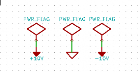
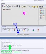
I got the power flags to 'stick' and the ERC fails with error code 0 (passes).
For some reason I cannot find a simulate icon now.
I don't think I opened it any differently (different module?).
I am starting to recognize the organizational characteristics.
.pro is the entire project, 'managed' by KICAD, and the .sch schematic is 'managed' by Eeschema...
I thought the simulation was done in Eeschema but I can't find the Simulate icon.
??
Krap...I opened it again and there are three errors on ERC again.
I guess I get practice adding the flags again.
I guess I get practice adding the flags again.
I haven't used it since 2014 which pre-dates simulation capabilities I think. I do remember there was quite a learning curve but once you get used to it, it becomes pretty easy 🙂
Maybe it didn't save properly last time.
Tony.
Maybe it didn't save properly last time.
Tony.
- Status
- Not open for further replies.
- Home
- Design & Build
- Software Tools
- KICAD newbert question