Nice work Brian, what driver did you use in your POC3?
The Dayton PA-310 12" pro audio driver.
I'm contemplating POC4 at the moment - similar design, but using something capable of a bit more output - the Eminence Kappalite 3012LF. Box size and layout should be fairly similar, but the Kappalite's 9mm Xmax means the box will be capable of a bit more SPL.
And so it does I see. Nice work.TBW100 fits with stock dimensions.
Do you think clearance for the motor to breathe would have made a difference in cooking the driver?
Keystone Sub Using 18,15,&12 Inch Speakers
Possibly, but so would not bypassing the limiters on my iTech 😀
There are small vents where the magnet meets the basket as well, lots of ventilation going on in these drivers.
One would have to try both ways and measure the difference in response.
Edit: I used Art's sketch as well as Oliver's drawing, I made my own drawing with in Sketchup that showed all the finer details I had decided on.
Sent from my iPhone using Tapatalk
Last edited:
The ring of holes directly vent the magnet-end of the voice coil. I'd leave those as unrestricted as possible, as you can get quite a lot of air movement when excursion gets going.
A thermal imaging camera would be really cool to check these. Wonder if I could sneak some kit into the lab...
Chris
A thermal imaging camera would be really cool to check these. Wonder if I could sneak some kit into the lab...
Chris
And so it does I see. Nice work.
Do you think clearance for the motor to breathe would have made a difference in cooking the driver?
What am I missing? Looks to me the voicecoil should be getting plenty of air in that position or in any tapped horn type enclosure (positive, straight, or negative flare).
What am I missing? Looks to me the voicecoil should be getting plenty of air in that position or in any tapped horn type enclosure (positive, straight, or negative flare).
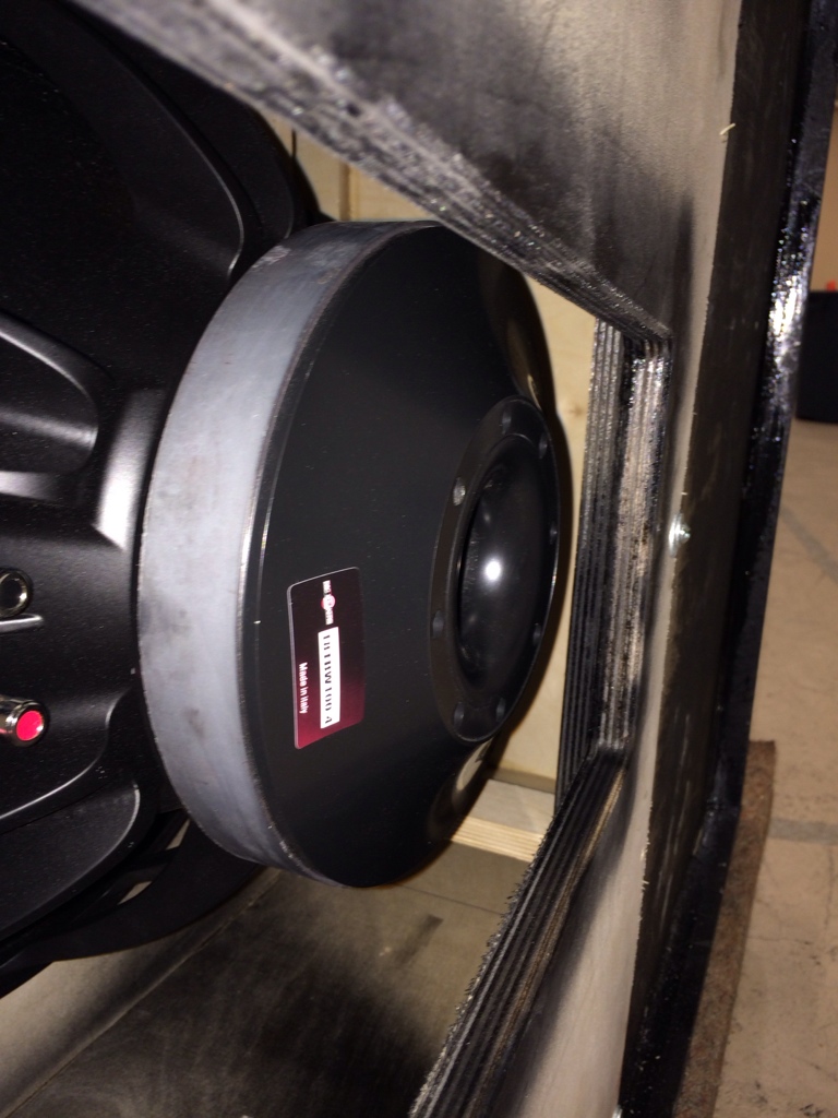
Your eyes do not deceive you. This cabinet is not built to spec...
Your eyes do not deceive you. This cabinet is not built to spec...
My cabinet is not built to spec?
Sent from my iPhone using Tapatalk
My cabinet is not built to spec?
I think that's the case.
Is the driver recessed into the baffle?
The gap is around 1/2".The gap between the motor and the inside of the front panel looks like it could be more than the thickness of the plywood?
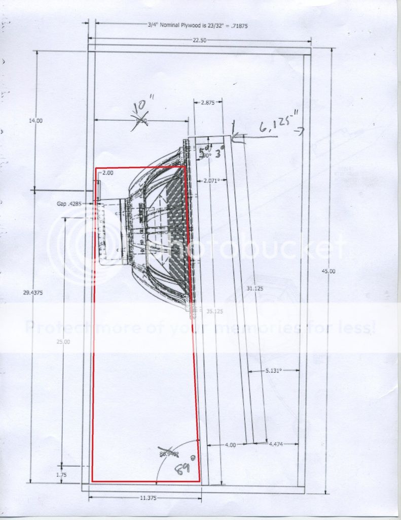
There is an error in the position of the baffle in Oliver's dimensions due to my small drawing not having been corrected to the actual full size lofting of the cabinet. After measureing the actual build dimensions I caught the error now, they are shown below on your layout.
Note there are 9 braces in the cabinet:
Brace 1 (two units) in the first portion of the horn
Brace 2 (two units) in the second portion of the horn
Brace 3 in the second portion of the horn centered on the driver
Brace 4 between the top of the horn path and top of the cabinet
Brace 5 between brace 4 and the front of the cabinet
Brace 6 (two units) "wing braces" either side of the Keystone exit. Braces 6 have right angle brackets on the front of the cabinet that are T nutted in place to facilitate removal of the Keystone panel for driver installation.
Art
Attachments
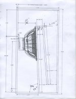
Other than loosing the keystone effect, is there any reason I could not make the opening on the side? I would prefer a narrow and deeper cabinet. Opening in pic is not to scale. I realize I would have to keep the access panel. Thanks
The way the panels are designed, you would have to re-shape the keystone exit to be wider in the top and more narrow in the bottom
If this would be able to execute, it would be cool to be able to remove the driver throught the hole side-ways, to be able to exclude the access panel.
If this would be able to execute, it would be cool to be able to remove the driver throught the hole side-ways, to be able to exclude the access panel.
Last edited:
Keep the exit to around 6" wide at the top, and make it no higher than the original design and there should be no major concerns, as long as you heavily brace the panels, the "wing braces" will need to be turned to around 45 degrees. The exit will have slightly less area than the normal Keystone, which will result in a a slight reduction of the low frequency cut-off frequency, and slightly less upper response in the 70-100 Hz region.Other than loosing the keystone effect, is there any reason I could not make the opening on the side? I would prefer a narrow and deeper cabinet. Opening in pic is not to scale. I realize I would have to keep the access panel. Thanks
The non- symmetrical lay out may result in more distortion at high drive levels.
Art
Actually, how hard would it be to simply turn the insides of the cabinet 90 degrees, readjust the internal panels to match hornresp and put the Keystone opening on the narrow side of the cabinet? That would keep symmetrical loading on the driver and allow for larger magnet drivers to fit.
That would not be difficult, but the reduction in frontal area also will reduce frontal output slightly.Actually, how hard would it be to simply turn the insides of the cabinet 90 degrees, readjust the internal panels to match hornresp and put the Keystone opening on the narrow side of the cabinet?
- Home
- Loudspeakers
- Subwoofers
- Keystone Sub Using 18, 15, & 12 Inch Speakers