The reference to fresh eyes was from my end, seems I'm going round in circles and round the bend...
Agree, need 1.2V on Q43b, probably due to increased current(and volt drop) through R102, R103. If Q39 is on it will drain current. Likewise Q40 and Q42.
Maybe work out where the bulk of this current is going.
Calculate current through R102 by measuring volt drop across it. Repeat for R103.
Expect R103 current to be less than 50% of R102. Would point to Q39...Q41
otherwise Q43,4. Compare with working side.
Check C30 for solder bridge.
Is LED D39(protection) on
yes I feel the same-
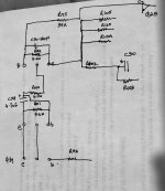
I will check the voltage drops, and will draw a new version of the Q40/Q41 circuit as the emitter of Q41 goes to R109,R110 and R105 as well as R102
Will check LED and solder joints (have been redoing some and using the big magnifying glass..
Thanks again
I will check the voltage drops, and will draw a new version of the Q40/Q41 circuit as the emitter of Q41 goes to R109,R110 and R105 as well as R102
Will check LED and solder joints (have been redoing some and using the big magnifying glass..
Thanks again
Bad unit- R102 -60v A =00027/ R103 -3v (fluctuates between -2.5 and -3.2) A=0.00008
Good unit R102 -55- A=0.00025 /R103 -6v A=0.00016
The LED (39 is on on both units- I think it is an indicator rather than protection
There is no solder bridge ob C30
Good unit R102 -55- A=0.00025 /R103 -6v A=0.00016
The LED (39 is on on both units- I think it is an indicator rather than protection
There is no solder bridge ob C30
Your diagram helped a little. Q41e connects to the 71V rail, I incorrectly had it on the other side of R102, that's why I was looking for R102,3 currents.
Bad unit has an extra 5Vdc drop across R102 (.02mA). Does not appear to be going through R103, points to Q39,40, 42. Some of these already replaced, will check orientations...
Bad unit has an extra 5Vdc drop across R102 (.02mA). Does not appear to be going through R103, points to Q39,40, 42. Some of these already replaced, will check orientations...
Q39,40 2SC2378, ecb, insert as per board icon.
Q42, 2SA954, ecb,
Is the marked transistor Q42, schematic has it as TO-92.
Looks like recently replaced, leeds have not been trimmed?
What is it, 2SA...

Q42, 2SA954, ecb,
Is the marked transistor Q42, schematic has it as TO-92.
Looks like recently replaced, leeds have not been trimmed?
What is it, 2SA...
I am going to spend time looking for PCB cracks, I suspect the problem may be mechanical- will report back
So I have re-soldered any suspect connections, tested continuity and no success-tested the quad diode/dual diode for voltage drop (they are both OK)
I have revised my approach to consider that the relay drive circuit is working, and there is some other factor causing the relay to switch on and off- If I turn the offset control the relay "buzzes", that is it is switching on/off very fast- or does not have quite enough power to stay closed.
My brain (or what is left of it) is really hurting on this one- none of the voltages make any sense to me- why does Q25 have 65v on the collector, and Q30 has 5.x volts on Emitter and base.
If anyone can have a look at this, I really need some help with this one.
I will post more voltages tomorrow
To me it is some problems in cascode (Q20 & Q22) or in pre drive of output transistors.
I would remove Q25 and Q26 and pull up R51 and R52 one leg from the board.
After that you know for sure where the problem is.
If you still have DC output on speaker relay, you should check predrives transistors Q29, Q31, Q30 and Q32. You have probably leak in some of the transistors.
With disconected resistors R51 and R52 chek for symetry on the cascode collectors (Q20 and Q22), if there is no symetry check cascode and transistors before.
@pitbul- thank you, I think you are right.
Here are the voltages measured before pulling R51/52.
e c b
Q20 64.4 1.4 63.7 note collector jumps to -2v on relay click
Q22 -65.5 -5.7 -64.7
Q25 2.2 67 -1.9 Note collector should be 1.8
Q26 -5.6 0 -1.7
Q29 0.3 68.4 -1.8
Q30 -5.4 -68.4 -5.6
Q31 0.22 67 0.3
Q32 0 -68.1 -5.2
I will now lift the resistors and pull and check each transistor, though I have checked Q30, Q31,Q32 and they all test good on the Peak transistor tester
I will report back with Q25/Q26 removed and R51/R52 lifted
Thanks again
Peter
After removing Q25/Q26 and lifting R51/R52 the clicking has stopped and there is no DC on the output (which is such a relief!).
Q25 and Q26 test good
The collectors of Q20 and Q22 are not quite symmetrical - Q20c=65.7v, Q22c=61.7v
I will check the transistors prior to these and report back
Q25 and Q26 test good
The collectors of Q20 and Q22 are not quite symmetrical - Q20c=65.7v, Q22c=61.7v
I will check the transistors prior to these and report back
The dual fet and transistors Q4, Q5,Q6,Q7,Q8 and Q18/Q23voltages all match the circuit- which is a relief.
Q1 e and b are low (4.9v vs 7v and 5.8v vs 7.6v), so I will replace the 2sc2378 with a KSC1845 and see if that makes a difference- if not then I will lift and test all the passives
Q19,Q14 and Q16 are all as per the circuit. Q12c is 5.8v vs 7.5v- which aligns with Q1.
On the negative voltage rail Q21c is -5.7v vs -5.1v which given the measured rail voltage is less than the circuit may be a little odd.
again thanks
Peter
This measurements on collectors are not critical, because you don't have exact mid point, to me they are correct.
Double check pre drivers and output devices.
Double check pre drivers and output devices.
Q29/Q30 measure good.
Q31/Q32 drivers measure good, though the 2SA1112 has Hfe of 102
All the outputs measure good- Hfe range form 112 to 165
Even with the drivers and outputs disconnected the relay problem was there- which suggests that the problem in on the main board (up to Q29/Q30)- would it be wise to install Q25 and R51 to see if the problem returns?
Last edited:
Try replacing the relay, or swapping the relays between the two units as a test.
Just because a relay clicks, doesn't mean the contacts are good.
Contacts can fail even when switching small signals in a low current, high impedance circuit.
The circuit that decides to trigger the relay may also be looking for a change to occur after the relay has switched, and if it doesn't see it, it just keeps trying.
I work with industrial controls and relays are the #1 failed component in the plant, both small signal and power types.
@techtool- completely agree on the relay. I have already replaced this one, as the original had one leg that was short, possibly making contact with the underside of the PCB less
than optimum- sadly the new relay behaves the same as the old one-
I put a DMM between the collector of Q25 (still not fitted as per @pitbul suggestion) to see what voltage was there and that forced the relays to disconnect.
If is is not the input section- which seems fine, and the output section also seems fine- then when they connect via Q25/Q26 and R51/R52 the problem occurs.
It really has me flummoxed!
So, I think that you should check for cracks on pcb circuit board.
Your info about putting probe on collector of Q25 is insufficient. Where is the second probe connected?
Q25 and Q26 are transistors which conducts when too much current flow to the speaker, Q27 and Q28 are sensing amplifier, resistors R55 and R53 are voltage dividers on transistor Q27 base (for negative part of the signal R56 and R54 do the job for Q28 base).
Same point as collector Q25 is speaker output, check voltages on this point, if it is different than your collector Q25, it is obvious you have crack on the board.
R96 resistor is feeding element to your relay drive circuit, it senses offset voltage, after that resistor you have bipolar capacitor of 100uF which is possible point of leak. Try to pull out this capacitor and see what happens then. This is what came to my mind after your tryouts.
After trying to write some info about the relay, I found on schematics that this amp have info about speaker voltage (two sets of cables to the speaker, one for current feed and another one for voltage sense on speaker connection).
With switch S2 you enable or disable written way of return path. If that switch is with bad contacts (off position means that you have connected speaker return path with R92-470R to the C12), maybe amplifier doesn't know what is happening on it's output. Try to check switch, does it have good connection, or it deteriorated with time.
Good practice is to once a week change position of all mechanical switches to prevent contact failing.
If switch S2 is bad, simply connect wire from +speaker terminal to +sum terminal and after that amplifier for sure will know what is on the speaker output.
C12 is bypassed by R26-22R, so maybe it will not have any relevance in this testing.
I vote on this switch that it is the problem.
Last edited:
- Home
- Amplifiers
- Solid State
- Kenwood L08m relay problem