Morning Mooly
i see it as a faulty semi or a resistor that is open or drifted ... as said to my opinion checking voltage drop will show something
i see it as a faulty semi or a resistor that is open or drifted ... as said to my opinion checking voltage drop will show something
Aidan... when you have pulled those two transistors I would reset the bias to zero again before powering up. Then check the offset, then reset the bias it all looks OK.
Fingers crossed, if one or both of those limiters was leaky then it could give a raised offset and yet the amp still appear to work.
I'll look in again in a little while.
Fingers crossed, if one or both of those limiters was leaky then it could give a raised offset and yet the amp still appear to work.
I'll look in again in a little while.
Morning Mooly
i see it as a faulty semi or a resistor that is open or drifted ... as said to my opinion checking voltage drop will show something
I think one of those limiters could well have taken a hit and become leaky. Leaky as in a couple of hundred ohms or less... and the amp would still appear to work up to a point.
I'm hoping that's what it is. Can't see it being anything front end related... its some collateral damage from the original fault. I hope 😀
morning sakis! nice to see you again sir.
well, i did all the resistors in the left channel. all within spec, or higher by less than 5% (and they, if i remember, were high value resistors to start). and your method is precisely the way i usually attack tube radios that i work on/collect. and yes, i remember seeing that AM radio trick. works great. also works great with calibrating a given frequency by tuning the main receiver and then using the AM radio to find the null point. when on same frequency the radios exhibit a null point where modulation drops when on same freq. works same like a grid dip meter, no?
mooly. i removed Qe9 and Qe11. the DC offset rose to .225 (from .209V) and the bias has now dropped to 0V, with no change with bias adjustment.
aidan
I'm thinking...
One more thing we can look at. Do you have any small pf range caps. Say 10 or 22pf ?
One more thing we can look at. Do you have any small pf range caps. Say 10 or 22pf ?
actually, i have 3 o'scopes.
one is from 1931 (!), TMV-122-B, by RCA. second is from 1966, type 304-H, Dumont Labs. third is a modern one. modern, yeah right, me? 🙂 i bought it in late 90's, model LBO-508A, by Leader corp. dual trace, 20 mhz. i am ashamed to admit that i have completely forgotten how to use it. the hobby work i do is usually on boatanchor radios, and i have never had to use a scope with them. i've always managed with my dvm, vtvm, signal generator, audio generator, and my ears to get them running. i literally have hundreds of radios, many on display in my man room, many more in the basement used for parts, experimenting, etc. SWMBO (wife), tolerates my hobby, to a degree. 🙂 she has her limits, and they begin at the door leading out from my man-room lol
aidan
yes, i believe i do. or, at very least, down to .0005, but probably can scrounge a few lower somewhereI'm thinking...
One more thing we can look at. Do you have any small pf range caps. Say 10 or 22pf ?
aidan
Focus please
I am not talking about how many OHMS is every resistor ..this is an initial test
I am talking at operation mode no signal no load and asked you to measure voltage drop on every resistor even better comparing to the working ch
If you have for example excessive voltage drop in one resistor that means that one of your semis is pulling more current than an other or resistor failure ..That is an indication of leak in any of your semis or resistors ( semis and resistors can also leak under voltage and go open ... failure is not always on or off it can be about failure also might occur only the semi is supplied )
Sakis
You have a scope 🙂 He has a scope !!! Three scopes.
I'll tell you what I'm thinking, before the scope revelation 😉
Removing Qe9 and 11 should have had zero effect. If you quickly check them on your meter do they read faulty (very low and leaky) ?
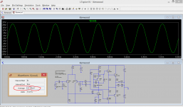
I think there could be two issues at work here now. If its oscillating a small (and it must be small) cap across Ce11 could prove it.
Get your scope fired up...
I'll tell you what I'm thinking, before the scope revelation 😉
Removing Qe9 and 11 should have had zero effect. If you quickly check them on your meter do they read faulty (very low and leaky) ?
I think there could be two issues at work here now. If its oscillating a small (and it must be small) cap across Ce11 could prove it.
Get your scope fired up...
yes, i believe i do. or, at very least, down to .0005, but probably can scrounge a few lower somewhere
Three noughts 5, whats that in old money, 500pf ? to big by a factor of 10.
aidan
Focus please
ok. it's early here. mooly and i started at about 2:30 A.M. local. good chance i was bleary eyed at the start 🙂
agreed. you said so yourself. "Make sure that you don't have any resistors open especially around the driver area . Check with the DVM but if anything looks suspicious remove it from the board and measure outside the circuitI am not talking about how many OHMS is every resistor ..this is an initial test
Kind regards
Sakis "
all within spec, or 5% for a couple.
yers, i recall. what you suggested is that the DC offset level was caused by a "leaky" transistor, that we couldn't see with the meter. but, is it really the correct way to diagnose a problem by constantly, and repeatedly comparing it to the working channel? i mean, this is a hobby for me, and it is your profession. i will defer to the pro's here, of course.I am talking at operation mode no signal no load and asked you to measure voltage drop on every resistor even better comparing to the working ch
is this when we compare it to the working channel? so, mooly, sakis, just wondering which avenue we should pursue here. it's all a little overwhelming for me this gear is.If you have for example excessive voltage drop in one resistor that means that one of your semis is pulling more current than an other or resistor failure ..That is an indication of leak in any of your semis or resistors ( semis and resistors can also leak under voltage and go open ... failure is not always on or off it can be about failure also might occur only the semi is supplied )
aidan
mooly, sakis, just wondering which avenue we should pursue here. it's all a little overwhelming for me this gear is.
aidan
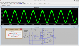
In a nutshell... the offset you have is small and doesn't suggest a damaged or non functioning device or component. Such things tend to cause the output of the amp to swing toward the rails. This is more subtle.
Causes... the most likely at this point is a form of instability. A tiny cap across Ce11 would nail that as the cause. If it were unstable the adition of the cap would kill the oscillation dead.
You say you have a 500pf cap (must be 100v or more because it sees full rail voltage at times) then adding that across Ce11 would still prove the point but its to big to leave in... it would limit the amplifiers high frequency response.
this is the approach i would use in an amplifier in your condition
I dislike to cure electronics with medicine or band aids i like to trace the reason of instability and eliminate before countermeasures are needed
Kind regards
Sakis
I dislike to cure electronics with medicine or band aids i like to trace the reason of instability and eliminate before countermeasures are needed
Kind regards
Sakis
- Status
- Not open for further replies.
- Home
- Amplifiers
- Solid State
- Kenwood KA-3500 and my blooper