Hmm, it's really hot today so i am going to do it tomorrow!
So we are going to remove the transistors in both channels, but first build op the left channel again!
The only thing about the pinouts.
The ones that connect trough emitter, then you can measure wich leads on the circuit bord are connected, and you know what's the emitter, and then you only need to know base or collector right?
But on the circuit bord there isn't anny Arrow or anything, so if I found the emitter, I will measure another thing for the base or collector?
Just remember to do a first time power on with a 50 watt bulb in series with the mains... this will save you some transistors if something is not right... saved me countless spares over the years....
Hmm, it's really hot today so i am going to do it tomorrow!
So we are going to remove the transistors in both channels, but first build op the left channel again!
The only thing about the pinouts.
The ones that connect trough emitter, then you can measure wich leads on the circuit bord are connected, and you know what's the emitter, and then you only need to know base or collector right?
But on the circuit bord there isn't anny Arrow or anything, so if I found the emitter, I will measure another thing for the base or collector?
We remove all the transistors from both channels to make it safe to work on, safe as in nothing gets zapped.
The pinouts have to be correct. Those diagrams should help, but you should also look at the data sheet and make sure you know which lead is which on the transistor sitting on the table in front of you.
Look at the circuit board and locate the other components that go to say the base and make sure you fit the new transistor correctly.
Also, you can look at the data sheet for the originals and make a drawing of B, C and E of the PCB for each and then carry the new ones across.
If you want you can post a clear picture of each and we'll see if it looks correct.
It might be a good idea (for your reference) to take a picture of the board with the originals in place.
Also I didn't get as far as replacing the two front transistors, but you'll be such a pro after these you'll suss them out in no time 😀
Well mooly, I removed everything you said (q15 trough 22 and 11,12,23,24)
But why don't we remove: q13,q14 and q7,8,9,10?
Start to rebuilt now 🙂
But why don't we remove: q13,q14 and q7,8,9,10?
Start to rebuilt now 🙂
Q13 and 14, well I would be very surprised if there was a problem with those tbh but we'll see as we get on to testing. The others are those I mentioned above 🙂 saying you'll be a pro and able to suss them out. Yes, we should replace those too using the 2N5550's.
Remember, one channel at a time and don't switch it on.
Remember, one channel at a time and don't switch it on.
Well replaced, Qm11 and Qm23 with leg bending, and checking it 3 times (with data sheet and checking the circuit bord, and the old one 🙂 )
Also replaced Qm15 and Qm17 (after checking it 3 times, it was instant with the old one, so no leg bending necesarry)
Also replaced the outputs 🙂
Also replaced Qm15 and Qm17 (after checking it 3 times, it was instant with the old one, so no leg bending necesarry)
Also replaced the outputs 🙂
That all sounds good. If you want to post pictures to be sure, then that's OK or, if you are happy then that's fine 🙂
Check that the metal tab of the outputs doesn't read short circuit to the metal heatsink. If it did it would indicate a problem with the insulating kits.
Important
In post #65 for some bizarre reason I mentioned replacing the front end transistors (Qm7,8,9 and 10) with 2N5550's. That should of course be using the 2N5401's (the PNP's). Apologies for that.
Can you figure the connections for those ?
After that, and we are almost ready to test (not today 🙂)
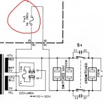
The mains fuse at the transformer (F1) is taken out and we attach a 60 or 100watt bulb across the fuse holder. Make sure the wiring is safe to the bulb.
Next we turn the bias pre-sets VRm4 and VRm5 to maximum resistance. If you put your meter on ohms (probably going to have to be 20K range) and put the red meter lead on the emitter of Qm13 and the black lead on the base and then turn the pot to the end that gives the highest reading. It should be around 2300 ohms but other components will alter that reading. Just turn it to the end that gives the highest resistance.
And that should be just about ready to test for real.
Check that the metal tab of the outputs doesn't read short circuit to the metal heatsink. If it did it would indicate a problem with the insulating kits.
Important
In post #65 for some bizarre reason I mentioned replacing the front end transistors (Qm7,8,9 and 10) with 2N5550's. That should of course be using the 2N5401's (the PNP's). Apologies for that.
Can you figure the connections for those ?
After that, and we are almost ready to test (not today 🙂)
The mains fuse at the transformer (F1) is taken out and we attach a 60 or 100watt bulb across the fuse holder. Make sure the wiring is safe to the bulb.
Next we turn the bias pre-sets VRm4 and VRm5 to maximum resistance. If you put your meter on ohms (probably going to have to be 20K range) and put the red meter lead on the emitter of Qm13 and the black lead on the base and then turn the pot to the end that gives the highest reading. It should be around 2300 ohms but other components will alter that reading. Just turn it to the end that gives the highest resistance.
And that should be just about ready to test for real.
I written the q7,8,9,10 right on my paper, so I bought enough 2n5401's haha!
But I haven't replaced them yet, should I do that or will you be surprised if it is in that transistors?
Need to find a 60 Watt bulb here.. Since 2012 they are forbidden in the Netherlands (not in the uk?).
vr4, and vr5 are set to max resistance.
But I haven't replaced them yet, should I do that or will you be surprised if it is in that transistors?
Need to find a 60 Watt bulb here.. Since 2012 they are forbidden in the Netherlands (not in the uk?).
vr4, and vr5 are set to max resistance.
Last edited:
I would be surprised tbh. They are in a very low current and low stressed part of the circuit.We can leave them for now and see how it all shapes up under test.
60 or 100 watt is OK. Even a 40 watt might work as the current drawn will be low. Not sure whether 60's are banned here, I don't think so, not yet.
60 or 100 watt is OK. Even a 40 watt might work as the current drawn will be low. Not sure whether 60's are banned here, I don't think so, not yet.
can't do better then 40 watt.. If that isn't good I need to find a shop that sells old fashion bulbs haha.
The metal part of the output transistor, doesn't measure short circuit with the heatsink I think.
Meter on 200k mode:
Red probe on screw other little part that's mounted on heatsink)
(red little dot on this photograph, not my own foto http://image.noelshack.com/fichiers/2011/32/1313343767-p81412102-2da0e18280.jpg)
q19: -92.16
q21: 00.7 (on 2k mode: 1400 and going up)
Black probe on screw other little part:
19: 1. (so no connection at all)
21: 00.8 ( 2k mode 686 and going up)
But the heatsink is bare metal under the transistors, with some coolpaste on it (wich i am gonna replace if it works properly)
Last edited:
my fault, heatsink is not directly bare metal haha, it's a sort of little plate with coolpaste that's mounted on the heatsink!
So it should be all fine!
going to replace coolpaste though.
So it should be all fine!
going to replace coolpaste though.
Sounds like we are ready to test then. Solder wires to the bulb and solder those across the mains fuse holder so the bulb takes the place of the fuse. There are two mains fuses shown on my diagram (one around the voltage selector switch) but its the main fuse Fm3 that you replace with the bulb.
Bias pre-sets turned to maximum resistance.
100% happy with all transistor connections.
I think that's everything covered... so we should be ready to switch on. No speakers to be connected yet.
The bulb should flash brightly as you switch on and then go out (or be very dim). If it stays lit then switch off as there is a problem.
Hopefully the bulb is out. Now measure the DC voltage on the speaker output fuse Fm1.
It should be zero.
If you get that far and all is OK then its looking good but don't connect speakers yet.
Attachments
Well, The 60 watt bulb broke on my way home 🙁.
But tested it with the 40 Watt, and as you said, it firs lit up brightly and then goes into very verry dim!
I used the fuse with 3.15 a on it because without that one it doesn't switches on.

And for checking the 0vdc, I measured the fuse that's next to the main amp (old picture)

But tested it with the 40 Watt, and as you said, it firs lit up brightly and then goes into very verry dim!
I used the fuse with 3.15 a on it because without that one it doesn't switches on.
And for checking the 0vdc, I measured the fuse that's next to the main amp (old picture)
Sounds good so far. Hard to make out in the pictures but it should be the mains input fuse. (Models for different countries and locations vary on fuse and safety requirements)
And is there zero volts on the speaker fuse ?
And is there zero volts on the speaker fuse ?
the zero volts is on the speakers fuse ( and that I know for sure, because left and right have a seperate fuse).
About the models, the one my mom bought when she was young, has for example no switched outputs, and this one has. My moms ka 1500, hasn't got the 3.15 volt fuse.
But it was in series so it was ok 🙂.
About the models, the one my mom bought when she was young, has for example no switched outputs, and this one has. My moms ka 1500, hasn't got the 3.15 volt fuse.
But it was in series so it was ok 🙂.
Excellent so far.
Next step... carefully turn up the bias preset for that channel. The bulb should start to glow. If it does, then turn the bias back down again.
Next step... carefully turn up the bias preset for that channel. The bulb should start to glow. If it does, then turn the bias back down again.
hmm, If i turn the bias pot the verry very dim light bulb dims even further? Maybe I made a fault and turned it already up at max before testing?
Last edited:
Don't panic just yet 🙂 Maybe you just have the bias pot at the wrong end.
Lets just see what the supplies are first before we do anything. Turn the bias pot so the bulb is at its dimmest. Very carefully measure the DC voltage on the metal tabs of the output transistors. Be very careful. Measure from ground to each. What do you get approximately ? One will be a plus voltage and one a negative.
Lets just see what the supplies are first before we do anything. Turn the bias pot so the bulb is at its dimmest. Very carefully measure the DC voltage on the metal tabs of the output transistors. Be very careful. Measure from ground to each. What do you get approximately ? One will be a plus voltage and one a negative.
- Status
- Not open for further replies.
- Home
- Amplifiers
- Solid State
- Kenwood Ka-1500 sounds weird (youtube link included)