1. So for testing the transistors there are more then 1 test.
-The one from the site you gave me. (B To E, and B to C)
-The one you let me do at first (C to E and C to E)
At the first one you test them like they are 2 seperate diodes and (and when you measure you got results like 500 to 1000 ohm and if you switch the red and black probe to infinity
At the second one you test if there is a short circuit between the '' 2 diodes'' trough the base, at one time but not where the short is
2. So if I get it right, when set on diode mode (what's in the ohm range) he isn't testing resistance in ohms but just giving mV's?
But about the amplifier, how to go further?
I think for the right channel (that I fried haha) I need new output transistors, and at least 1 driver transistor Qm18. Because now it keeps blowing fuses out.
And for the left channel, how to get on, the only thing I found strange was that over the driver transistors there only were high voltages and not the 0.5 volt like you said. Also som of the resistors look a bit weird (not shiny anymore), but measuring gives me still good feedback. (comparing to the right channel)
The thing with the driver transistors is that we don't know which is bas/ emitter/ collector, because you said that the volt drop across the bas and emitter must be 0.7 volt. But the only 0.7 volt was over pin 1 and 3 (most left and right) in the right channel before blowing it up.
Not over the middle one and the one with the arrow?
The most important thing you can do is familiarise yourself with how the transistor symbols are drawn on paper and which is the collector, base and emitter. All the transistor tests done with the meter on ohms and diode range are basic first line checks, they don't tell us anything about the gain of the device or even if its slightly leaky... they are just very basic tests, but they do show the majority of faults. 95% of failures are the device going short circuit C to E.
The circuit diagram tells us which is B,C and E and from that we can fit replacements of any pin configuration so don't worry over that.
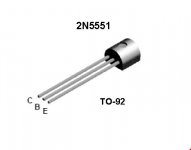
I would suggest using TIP41C and TIP42C for the outputs, either BC639 and BC640 or BD139 and BD140 or MJE340 and MJE350 for the drivers. The BD's and MJE's are a different package but would fit the PCB. And some 2N5551 and 2N5401 for the small signal devices if needed. You need solder braid. New fuses.
And you need somewhere to get the bits which for your country is something you'll have to look into. I wouldn't use ebay for any semiconductors, there are far to many fakes and duff devices around. Use a reputable supplier such as Farnell ? Radio Spares, Digikey or Mouser.
You need to measure those 0.47 ohm resistors to make certain they are OK. If you put your meter on the lowest ohms range and just short the leads together you will read the resistance of the test leads. For reading really low value resistors you need to subtract that from the actual reading. So if you the meter on its own reads 0.3 and testing a resistor reads 0.8 then you know the resistor is actually 0.5 ohms. It sounds like your meter isn't really suited to really low ohms readings but we can work round that. Measure all those 0.47 ohms. They should all be identical.
The circuit diagram tells us which is B,C and E and from that we can fit replacements of any pin configuration so don't worry over that.
I would suggest using TIP41C and TIP42C for the outputs, either BC639 and BC640 or BD139 and BD140 or MJE340 and MJE350 for the drivers. The BD's and MJE's are a different package but would fit the PCB. And some 2N5551 and 2N5401 for the small signal devices if needed. You need solder braid. New fuses.
And you need somewhere to get the bits which for your country is something you'll have to look into. I wouldn't use ebay for any semiconductors, there are far to many fakes and duff devices around. Use a reputable supplier such as Farnell ? Radio Spares, Digikey or Mouser.
You need to measure those 0.47 ohm resistors to make certain they are OK. If you put your meter on the lowest ohms range and just short the leads together you will read the resistance of the test leads. For reading really low value resistors you need to subtract that from the actual reading. So if you the meter on its own reads 0.3 and testing a resistor reads 0.8 then you know the resistor is actually 0.5 ohms. It sounds like your meter isn't really suited to really low ohms readings but we can work round that. Measure all those 0.47 ohms. They should all be identical.
hmm I think I just rebuilt the left and the right channel. So that there's no difference between the two ?
The right channel will be working great after that (as before I screwed it up), but what about the left channel, does it work again, or is there still something other wrong?
Edit:
Any pin configuration? Do you mean there are replacements with the left leg is b, middle c, right e, and a replacement with for example left is E, middle is b, right is C. Or that w're just going to bend the legs?
Last edited:
hmm found a good tutorial:
4 Ways to Test a Transistor - wikiHow
and Found a good consumer site, but first going to try it at the local audio shack!
Edit: I also get now what's an npn and a pnp transistor in the schematic, and what is the Bac/Emitter/Collector.
But to see what it's on the circuit bord I just need to look to wich leg a component goes (for example rm 76 is connected to the emitter of qm22).
Last edited:
Quite a good chance that rebuilding the amp will fix the original fault. Transistors come in all shapes and sizes with leads in every possible configuration although the output transistors will always be the same as the originals in that package. The driver replacements have a B-C-E (or E-C-B depending which way you look at it) pinout that should match the originals. The small signal ones are C-B-E so would need neat leg bending or even just fitting to the PCB as they are (with the legs in the correct places of course) and then a little turn by hand to separate the leads which are very soft and flexible. No problem 🙂
Well I'v been busy making a list, hope that you would check it and help me with the signal ones.
What I've got so far:
Main output
Q19 and Q20 (TD525 - NPN) For TIP41C
Q21 and Q22 (Tb595 -PNP) For TIP42C
Driver stage
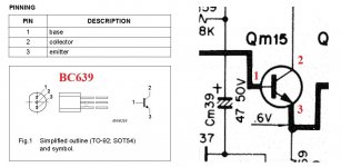
Q15 and Q16 (C1509- NPN) for BC639
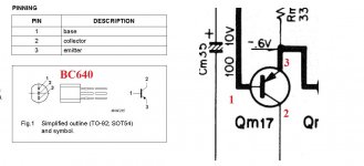
Q17 and Q18 (A777 -PNP) for BC640
Signal Stage
But now what I think is the signal stage, I see 3 types of transistors and you gave me 2 for that haha.
Q13 and Q14: (A721-PNP) for
Q11,Q12,Q23,Q24: (C1400 U76a - NPN) for
Q7,Q8,Q9,Q10: (A750 IE75 - PNP) for
So if I understand it correctly, they don't have the same pins on the place of the originals ( like if Original is BCE this one is CBE?)
What I've got so far:
Main output
Q19 and Q20 (TD525 - NPN) For TIP41C
Q21 and Q22 (Tb595 -PNP) For TIP42C
Driver stage
Q15 and Q16 (C1509- NPN) for BC639
Q17 and Q18 (A777 -PNP) for BC640
Signal Stage
But now what I think is the signal stage, I see 3 types of transistors and you gave me 2 for that haha.
Q13 and Q14: (A721-PNP) for
Q11,Q12,Q23,Q24: (C1400 U76a - NPN) for
Q7,Q8,Q9,Q10: (A750 IE75 - PNP) for
The small signal ones are C-B-E so would need neat leg bending or even just fitting to the PCB as they are (with the legs in the correct places of course) and then a little turn by hand to separate the leads which are very soft and flexible. No problem
So if I understand it correctly, they don't have the same pins on the place of the originals ( like if Original is BCE this one is CBE?)
Last edited:
That's a good start. Just be aware that the TIP transistors must be the "C" version which are 100 volt devices.
The signal transistors can all be replaced with those two type, the 2N5551 and 2N5401. There are many many alternatives for all these so if any aren't easily available then we can look for others. The pin out is different but no problem.
Those 0.47 ohms OK ??
You want solder braid. This kind of stuff. It makes it easy to remove parts without damaging the PCB.
60-5-5 - CHEMTRONICS - 3.9MM SODER-WICK DESOLDERING | CPC
Hmm is a 30 watt soldering iron enough to use with soldering braid?
I am going to the local audio shack tomorrow, but of they dont have the ones you said, do i need to give the codes of the original on the transistor or the code on the scheme?
Arent there any alternatives with the right pinout?
I am going to the local audio shack tomorrow, but of they dont have the ones you said, do i need to give the codes of the original on the transistor or the code on the scheme?
Arent there any alternatives with the right pinout?
The TIP41c... very dated. Low hfe gain, low power handling... I would use a larger trannie that is easier on the drivers... e.g. 2sd1047/ 2sb817 pair used in many nice sounding amplifiers. Although the TIP's are same size as the 525/526, the 1047/817 are a bit larger... I see no problems with it though. But since you are learning, go with what is comfortable and available to you. You might need larger mica insulations too...
Hmm is a 30 watt soldering iron enough to use with soldering braid?
I am going to the local audio shack tomorrow, but of they dont have the ones you said, do i need to give the codes of the original on the transistor or the code on the scheme?
Arent there any alternatives with the right pinout?
A lot depends on what you can get. Different pin outs for the small transistors is a non problem in practice. The original numbers won't mean anything to a supplier. All the devices I mentioned are common types but whatever you get need to be suitable (goes without saying) and also "complementary pairs" which all those devices are.
30 watts should be OK but its best to use a large bit that holds the heat. Here's the iron I use and solder braid "in action" 😀
http://www.diyaudio.com/forums/parts/127924-working-smd-how-do-without-specialised-tools.html
The TIP41c... very dated. Low hfe gain, low power handling... I would use a larger trannie that is easier on the drivers... e.g. 2sd1047/ 2sb817 pair used in many nice sounding amplifiers. Although the TIP's are same size as the 525/526, the 1047/817 are a bit larger... I see no problems with it though. But since you are learning, go with what is comfortable and available to you. You might need larger mica insulations too...
Very dated 😀 yes, but so is the amp they are going in 🙂
I will stick to the easiest way for now. But what I think is strange that the codes on the scheme give me Google results for alternatives, but the codes on the phisycal transistor don't.
There are more transistors out there than you can shake a stick at. It really does come down to what you can get, and if your shopping locally then that limits it further. You'll have to see what's on offer. If your not sure ask them to write down the device numbers they have and we'll look them up.
To give you an idea, in the 1970's and 1980's before PC's and internet the reference for all devices was a book called "Towers International Transistor Selector" and it listed in print all the specs for around 30,000 devices. That was in the 70's and 80's.
You won't get Japanese devices (2SA's 2SB's 2SC's and 2SD's) off the shelf. You have to go with standard well known types.
Did you see the link in the post... I forgot and added it as an edit.
I can send you some free 1047/817's... just pay postage... these are working pull outs from Adcom GFA-555ii where they are used as drivers...
@ K-amps, thanks for the offer, really nice!
The only thing is that I just bought a bunch of transistors haha, maybe in the future for like a upgrade or so? But first get the thing runnig well again.
To check pinouts and to see how to bend them, I found this site:
Semiconductor (Transistor, diode, IC) Cross reference
It would be nice if someone could confirm the trustability off this site haha. It would be very easy if I just type in the original transistor that's in the amp (on some points not the one in the scheme like the A721) and I can see wich leg is wich, and I can bend it right!
p.s, Orderd online tough, used conrad. Local radio stores had all my transistor but at a x3 price.
Like to help the local shops, but not tot much!
Edit: DAMN, checked my order list but I ordered the 2n5550 instead of the 2n5551.. (when searching on 2n5551 it links you to the 5550)
Last edited:
This is a good resource for detailed data sheets, just type the number into the blank box.
Datasheet catalog for integrated circuits, diodes, triacs, and other semiconductors, view
We know which leg is on the amp from looking at the diagram and the PCB. You can then look up a devices data sheet and figure out the connections but don't worry... we'll make 100% sure its correct before you switch anything on.
2N5550 is just as good for what we need here. Its the outputs and drivers that should be complementary, the others don't work in pairs of NPN and PNP so the 5550 is fine.
By the way... you are using a 50 watt bulb in series with the mains to power this thing on right? It will save additional burnt components during fixing... very essential for anyone working on an amp.
If you don't know what it is here is a link... you can make a simpler one yourself... I usually use a 200 watt bulb as i work with larger amplifiers... for this guy 50 watts should be enough.
http://www.vintage-radio.com/projects/lamp-limiter.html
If you don't know what it is here is a link... you can make a simpler one yourself... I usually use a 200 watt bulb as i work with larger amplifiers... for this guy 50 watts should be enough.
http://www.vintage-radio.com/projects/lamp-limiter.html
Last edited:
Well guys, got my order at home!
So I checked everything out and I think It goes like this:
The outputs:
(td525) For Tip41C : Goes instant, same pinout
(tb595) For Tip42C: goes instant same pinout
The drivers
c1509 For bc639 Goes instant, same pinout ( the one in the schematic is opposite of these both)
A777 for BC640 goes instant same pinout( the one in the schematic is opposite, so the a777 is already opposite then the one in the schematica)
Signal:
A721 For 2n5401
With flat side up looking at the bottom: (2SA721 pdf, 2SA721 description, 2SA721 datasheets, 2SA721 view ::: ALLDATASHEET :::)
A721:
1:E
2:C
3:B
2n5401:
looking from the bottom, flat side up:
1:E
2:B
3:C
a750 For 2n5401
A750 (really not sure acutally!!)
1:e
2:c
3:b
c1400 for 2n5551(not 100 procent shure)
c1400:
1e
2c
3b
2n551:
1e
2b
3c
Outputs are as you say, a direct replacement. For the others, we'll have to get you thinking in the correct "language" and get away from the 1,2 and 3 😀
Its going to have to wait 'till tomorrow 🙂 Don't do anything in haste. We'll go through each transistor one at a time and make sure you have them correctly fitted.
Its going to have to wait 'till tomorrow 🙂 Don't do anything in haste. We'll go through each transistor one at a time and make sure you have them correctly fitted.
ok! Will be replacing only the outputs tomorrow 🙂, and wait till you tell me what to do. I think I get what you want to say haha
First thing is to prepare the amp. This means removing the outputs and drivers from both channels, Q15 through to Q22. Be careful not to damage the mica washer insulating pads on the outputs (we should really have fresh thermal grease but we can get the amp working first). With the transistors removed use the solderbraid to clear any remaing solder from the PCB pads. You can also use ISO (alcholol) and a cotton bud to clean any flux etc from the pads. The pads and board should end up looking perfect.
With the transistors out we can now measure in circuit the four 0.47 ohm resistors and the four 330 ohm resistors. Just to be sure they are OK.
Now remove QM11 and 12 and 23 and 24.
Check RM49 and RM50 in circuit (should be 100 ohm)
Now we build one channel up.
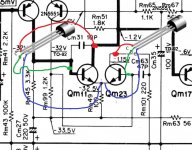
Replace QM11 and QM23 with the 2N5550. Look at the pinouts. The emitters connect together on the PCB. When fitted make sure that none of the leads are shorting to any other as you will have had to twist/bend the leads to get these to fit. Look at the data sheet again and confirm that the connections are correct. On the diagram the emitter is the one with the arrow. The base is the "middle" connection and the collector at the top. Remember on the diagram the other (right) channel is drawn "upside down"
Next we fit the NPN driver QM15 using BC639. Look at the diagram.
And the same for the PNP BC640 driver QM17
Now the outputs can be fitted. The TIP41C replaces QM19 and the TIP42C replaces QM21
Check using the low ohms range on your meter, that the metal tab of both outputs is isolated from the heatsink. There should be no continuity. Best to do that before you solder them in. You may get some reading with them soldered in but it must not be a short.
And don't switch anything on yet, there's more to do.
With the transistors out we can now measure in circuit the four 0.47 ohm resistors and the four 330 ohm resistors. Just to be sure they are OK.
Now remove QM11 and 12 and 23 and 24.
Check RM49 and RM50 in circuit (should be 100 ohm)
Now we build one channel up.
Replace QM11 and QM23 with the 2N5550. Look at the pinouts. The emitters connect together on the PCB. When fitted make sure that none of the leads are shorting to any other as you will have had to twist/bend the leads to get these to fit. Look at the data sheet again and confirm that the connections are correct. On the diagram the emitter is the one with the arrow. The base is the "middle" connection and the collector at the top. Remember on the diagram the other (right) channel is drawn "upside down"
Next we fit the NPN driver QM15 using BC639. Look at the diagram.
And the same for the PNP BC640 driver QM17
Now the outputs can be fitted. The TIP41C replaces QM19 and the TIP42C replaces QM21
Check using the low ohms range on your meter, that the metal tab of both outputs is isolated from the heatsink. There should be no continuity. Best to do that before you solder them in. You may get some reading with them soldered in but it must not be a short.
And don't switch anything on yet, there's more to do.
Attachments
- Status
- Not open for further replies.
- Home
- Amplifiers
- Solid State
- Kenwood Ka-1500 sounds weird (youtube link included)