Excuse me for being brief, I am an engineer, and after more than 20 years on various audio (...)
The same applies to me, so let's be brief ..!
fullscale
n=5
fo=1kHz
Rload = 15kOhm (maximum permissible load, otherwise the distortion increases.)
THD < 0.018%
#
It doesn't look bad at all for this trivial DIY circuit - and it will have its own sound profile.
Attachments

That was intentional!This is a mismatch of several techniques.
Yes, this is also always the standard case, it applies to the emitter circuit - completely independent of any feedback structure.There is a current conveyor visible composed of a diamond bufer driving two transistors that do the voltage to current conversion.
One should be able to let go of the dreams of the diamond at some point, it is the collector circuit and nothing else.
Aha, the working resistor (also known as the load) - ok. this can be connected to one of the supply voltage rails or to the reference potential called gnd.At this point a current driven Riaa network should be connected with it’s other side to gnd.
Any node (that seems to make sense) can be used, especially if it is a virtual zero. You have to be able to differentiate clearly between the static and the dynamic view. But we are all familiar with this.
Ok, which brings us to the ideal voltage source model. Or finally talking about dynamic internal resistances (of possible sources).A high input impedance buffer should provide a low ohmic output impedance.
That's total nonsense, because the realization of a negative feedback loop that you criticize here has worked for centuries - and has been used successfully since time immemorial.It’s output is the right point to connect a feedback resistor to the diamond output.
With respect, that is also stupid, because this path is very easy to walk on.Feedback from the current output is not the way to go to.
There is no current impedance (current riaa) and no voltage impedance (voltage riaa), not in the whole beautiful world! There is only one complex resistor, which is formed by reactances and effective resistances. Z(jOmega) you know and Z = U / I.Feedback is not to be used with a current Riaa network.
Of course, you can measure a proportional voltage if you dynamically connect a resistor (of any type) in parallel with a current source or sink. U = I * Z or I = U / Z.It’s one or the other no feedback and a current Riaa network or feedback from the output buffer with a Riaa network.
When I read your text, I get the impression that there is an ordinary RIAA network (actually it's just a resulting complex resistor, but let's not go there) and a current Riaa network (the same complex resistor). But this does not correspond to the physical facts.
"CFA's" ? current feedback amplifiers don't like -jX. Why? Because exactly this strange resistance (ohmic), i.e. Rf, also determines the bandwidth of the system, i.e. the upper cut-off frequency !?Point is however that CFA’s don’t like caps in the feedback path.
Dear Hans,
you can't knock me off my feet with so little content, with contributions devoid of content, but you can annoy me.
Well, if that's the case, then let's keep on simulating without any real background knowledge and impress our customers with empty phrases.Simulations will reveal the differences.
Hans
No hard feelings, but the closed season is over.
HBt.
The Magnificent Seven
For all those who have lost track in the meantime, the last iteration once again as a picture.

DIY also means (and not 1001 LT-Spice simulation fantasies) holding something concrete in your hand. Some kind of plan or inspiration. This design is such an example, a possible framework that you can try out and grow with. Don't worry, a simple ready-made soup is simply not the yellow of the egg.
Here you can learn by playing, I will be happy to answer any questions that might arise during a concrete implementation and will not leave you out in the rain.
And under the cloak of deferral,
I'll tell you that every third-party post in this thread ( even if it only consists of four letters ... "I see ..." [BB] ) gets a like from me.
HBt.
🧙♂️
For all those who have lost track in the meantime, the last iteration once again as a picture.
DIY also means (and not 1001 LT-Spice simulation fantasies) holding something concrete in your hand. Some kind of plan or inspiration. This design is such an example, a possible framework that you can try out and grow with. Don't worry, a simple ready-made soup is simply not the yellow of the egg.
Here you can learn by playing, I will be happy to answer any questions that might arise during a concrete implementation and will not leave you out in the rain.
And under the cloak of deferral,
I'll tell you that every third-party post in this thread ( even if it only consists of four letters ... "I see ..." [BB] ) gets a like from me.
HBt.
🧙♂️
Using a thousand words you attempt to mask that you obviously have no clue what a CFA is.That was intentional!
Yes, this is also always the standard case, it applies to the emitter circuit - completely independent of any feedback structure.
One should be able to let go of the dreams of the diamond at some point, it is the collector circuit and nothing else.
Aha, the working resistor (also known as the load) - ok. this can be connected to one of the supply voltage rails or to the reference potential called gnd.
Any node (that seems to make sense) can be used, especially if it is a virtual zero. You have to be able to differentiate clearly between the static and the dynamic view. But we are all familiar with this.
Ok, which brings us to the ideal voltage source model. Or finally talking about dynamic internal resistances (of possible sources).
That's total nonsense, because the realization of a negative feedback loop that you criticize here has worked for centuries - and has been used successfully since time immemorial.
With respect, that is also stupid, because this path is very easy to walk on.
There is no current impedance (current riaa) and no voltage impedance (voltage riaa), not in the whole beautiful world! There is only one complex resistor, which is formed by reactances and effective resistances. Z(jOmega) you know and Z = U / I.
Of course, you can measure a proportional voltage if you dynamically connect a resistor (of any type) in parallel with a current source or sink. U = I * Z or I = U / Z.
When I read your text, I get the impression that there is an ordinary RIAA network (actually it's just a resulting complex resistor, but let's not go there) and a current Riaa network (the same complex resistor). But this does not correspond to the physical facts.
"CFA's" ? current feedback amplifiers don't like -jX. Why? Because exactly this strange resistance (ohmic), i.e. Rf, also determines the bandwidth of the system, i.e. the upper cut-off frequency !?
Dear Hans,
you can't knock me off my feet with so little content, with contributions devoid of content, but you can annoy me.
Well, if that's the case, then let's keep on simulating without any real background knowledge and impress our customers with empty phrases.
No hard feelings, but the closed season is over.
HBt.
Nice try.
Hans

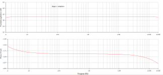
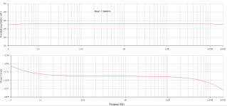
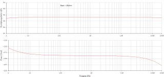
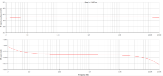
This is a big limitation, as nowadays preamps often have input impedance of 10 kohm or even much less. And you forgot to mention decreased gain and thus RIAA accuracy at low frequencies, when the load gets below 10k. I am sorry, the design is maybe a kind of fun for you, but nothing to be suggested as a DIY project for DIY community.Rload = 15kOhm (maximum permissible load, otherwise the distortion increases.)
Nonsense, whoever is evading (and obfuscating) here is you and not me.Using a thousand words you attempt to mask that you obviously have no clue what a CFA is.
Nice try.
Hans
HBt.
Now please leave the church in the village @PMA, I asked for the desired key data that a good (?) phono equalizer should have, in which points should it be better than, for example, your OpenAmp1 project - which I find just as good as Bonsai's or Wayne C's offer.This is a big limitation, as nowadays preamps often have input impedance of 10 kohm or even much less. And you forgot to mention decreased gain and thus RIAA accuracy at low frequencies, when the load gets below 10k.
So what load should the equalizer preamplifier be able to drive and how high can the THD be?
Realistic information please.
Nonsense! This thread is a carrier ... and one can or cannot draw information from it.I am sorry, the design is maybe a kind of fun for you, but nothing to be suggested as a DIY project for DIY community.
Greetings,
HBt.
Of course, I'm happy to make up for this immediately, I just didn't think it was necessary with these huge deviations from the norm!And you forgot to mention decreased gain and thus RIAA accuracy at low frequencies, when the load gets below 10k. I am sorry, (...)
😱
To keep these fabulous deviations visible, I increased the 470nF capacitors to 22µF (which would not have been necessary for either of the two guys, but I won't tell you why - because I have no idea about the matter ... that's what Mr. Hans P. wants to sell us, but he's very wrong ).
So if one can live with a THD of 0.01 % (actually only K2, i.e. a very good-natured distortion) under normal load conditions, you can go for the breadboard ..!
HBt.
Attachments
I forgot to mention that this thread here, called "Keine Ursache" is a continuation of that origin. This German phrase has several levels of meaning.
The friendliest one means:
you're welcome.
I believe that we should all play with open cards and be allowed to have controversial discussions.
#
A buffer or an extremely low-impedance (preferably frequency-independent) output resistor is of course desirable, but by no means a must. As far as I'm concerned, any standard hi-fi preamplifier can also have an input resistance of 50 ohms, 150 ohms or 600 ohms. It doesn't matter to me, I would just like to know what load is to be driven.
HBt.
@Hans Polak
You're absolutely right, I withdraw the question - because I know the answer to your loose insertion. Since you don't allow yourself to get carried away with answers even when tickled, one wonders what the point of your loosely strung together interjections is. Are they supposed to "feed" me?
As you can clearly see (I am not using the usual low-impedance output of an ADxyz, for example), there is a series resistor in front of the "evil" capacitor and another "very evil" parallel resistor to the C. At the same time, the internal resistance (if we look into the collector electrodes on the output side) is very high.
Just admit that you have only looked superficially. Please be accurate. As soon as I close the loop, your house of cards collapses, or to put it another way:
the situation changes dramatically. There is no zero, which leads to nasty instabilities.
Would you like to behave like an adult now so that we can at least uphold the rules of decency?
All the best,
HBt.
"CFA's" ? current feedback amplifiers don't like -jX. Why? Because exactly this strange resistance (ohmic), i.e. Rf, also determines the bandwidth of the system, i.e. the upper cut-off frequency !?
You're absolutely right, I withdraw the question - because I know the answer to your loose insertion. Since you don't allow yourself to get carried away with answers even when tickled, one wonders what the point of your loosely strung together interjections is. Are they supposed to "feed" me?
As you can clearly see (I am not using the usual low-impedance output of an ADxyz, for example), there is a series resistor in front of the "evil" capacitor and another "very evil" parallel resistor to the C. At the same time, the internal resistance (if we look into the collector electrodes on the output side) is very high.
Just admit that you have only looked superficially. Please be accurate. As soon as I close the loop, your house of cards collapses, or to put it another way:
the situation changes dramatically. There is no zero, which leads to nasty instabilities.
Would you like to behave like an adult now so that we can at least uphold the rules of decency?
All the best,
HBt.
Obviously you prefer discussing with yourselfWhat do you think of a seven BJT's EQ idea, an open design project. A collection of ideas? The best EQ that has ever been heard ..!
This is your professional view and contribution!?Obviously you prefer discussing with yourself
If we want to drive low-impedance loads, for example, 600 ohms, with a nominal output voltage of 2 Vrms across the entire audio range (preferably undistorted), then the circuit presented here (a learning tool, a discussion topic, a "functional" illustration, a sketch ...) is absolutely incapable of doing so.
But that should be immediately clear to everyone, as should the fact that phono equalizers are a dime a dozen, but have been since the first use of MM and MC systems.
The DIY enthusiast can draw on this diversity, and a student can implement their own ideas. After all, it's a learning process – the average audio DIY enthusiast will always repeat what they heard at the audio club or read nice things in a magazine.
HBt.
#
I'd be delighted if you could contribute something constructive to the success (of a virtual project and to the general learning process). You're experienced, a German physicist, have time... improve this circuit by changing the component dimensions. Please, I would be very pleased.
Originally, the question was which implementation of the function sounds better, also with regard to the override behavior of clicks and pops.
But that should be immediately clear to everyone, as should the fact that phono equalizers are a dime a dozen, but have been since the first use of MM and MC systems.
The DIY enthusiast can draw on this diversity, and a student can implement their own ideas. After all, it's a learning process – the average audio DIY enthusiast will always repeat what they heard at the audio club or read nice things in a magazine.
HBt.
#
You comment on the somewhat unfortunate introduction. Please, feel free, and continue commenting if it's good for you and flattering. You have the right to do so, but please refrain from personal insinuations of any kind; they're too manipulative.(...) I am simply commenting what I read.
I'd be delighted if you could contribute something constructive to the success (of a virtual project and to the general learning process). You're experienced, a German physicist, have time... improve this circuit by changing the component dimensions. Please, I would be very pleased.
Originally, the question was which implementation of the function sounds better, also with regard to the override behavior of clicks and pops.
Let's keep it short and concise
The OLG of the core is extremely easy to adjust, the maximum possible is +97.3dB with an upper cut-off frequency of just under 7kHz. Optimal currentfeedbacked results in a new upper cut-off frequency of >90kHz for the resulting +40dB (voltage gain). With an internal dynamic source impedance of approx. 820 ohms. Internal means or is equivalent to the output resistance of our amplifier.
Conclusion:
Everything can be adjusted by dimensioning the component values. Of course I'm keeping this big secret to myself 😉. This is because the complex negative feedback network with the pole and the zero must now be redimensioned. All so that we can drive low-impedance hi-fi preamps without using an additional buffer.
The most convenient way is to use a single NE5534 or better for the entire EQ. But now the faction of passive or current-riaa better'listeners is stepping on our toes.
The first adjustment screw:

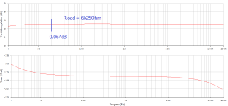
The amplification factor remains unchanged for the time being, as it was +20dB at f=1kHz. fh > 1MHz with Rload=10kOhm (standard value).
The amplification factor remains unchanged for the time being, as it was +20dB at f=1kHz. fh > 1MHz with Rload=10kOhm (standard value).
The second adjustment screw:

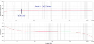
The amplification factor changed to +14dB at f=1kHz. fh > 1MHz with Rload=10kOhm (standard value). And so we tweak the countless screws until we have found the optimum that we like on the day and largely meets the required key data - the specifications. At the end of the day, we have a circuit that is different from the usual solutions, which makes the marketing department very happy. At some point, we start all over again because we realize that we seem to have made some kind of mistake.
If we don't want all that, we can use PMA's solution, the OpenAmp1-Project - this dish is already cooked, and taste well.
Your third, last sailor (aka Der Dritte im Bunde) has taken the bait....our last sailor takes a liking to the Netherlands.
I cannot see any personal insinuations from my side. Obviously you are riding a personal discovery tour that I did decades ago. Meanwhile I have done too much development and learning how to design and optimize this analogue stuff that any upcoming "new" investigations on that area are not really fascinating. As Karl Valentin once said: "Es ist alles schon gesagt, nur nicht von allen" (everything has been said but not by everyone).
If it was hooked, it is now sizzling in the frying pan of a hungry angler.Your third, last sailor (aka Der Dritte im Bunde) has taken the bait....
indescribably low impedance loads 🙂.(...) a big limitation, as nowadays preamps often have input impedance of (...)
And this problem has to be solved, either one don't buy a high-end audio preamp that's such a mean boy, or we go for the secret weapon, the fourth in the bunch:
"D' Artangan"
He will help all the other musketeers out of a tight spot.
#
The advertising and sales department is very happy about the mutation of the secret fourth, finally they can come up with great photos of the high-end PCB. A 100mWrms class A power amplifier, it also drives headphones crazy.
HBt.
Attachments

- Home
- Source & Line
- Analogue Source
- "Keine Ursache" : a still immature MM phono EQ idea