This gives me an effective ground plane prototype.
now I could have used a ground plane 😛
anyway
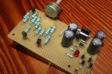
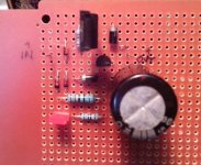
transistors are just random scrap, but shows to be convenient for moving around
resistors are very scratched from pulling in and out
but doesn't matter since I measure every time I move them
board could have been bigger though
Attachments


hi kean,
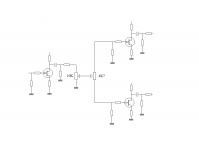
i've build a +rail of of your k-multiplier
using this part
q2 sa1873
q1 bc337
c1 1000uf/50v
d4/d1 1n4002
other same as schematic on your web
here my measuring
dc in 21.7v
dc out 20.14v
ac in 136mv
ac out 95mv
is this working good?
i've build a +rail of of your k-multiplier
using this part
q2 sa1873
q1 bc337
c1 1000uf/50v
d4/d1 1n4002
other same as schematic on your web
here my measuring
dc in 21.7v
dc out 20.14v
ac in 136mv
ac out 95mv
is this working good?
95mV output AC is waaay too high. It should be in the 100uV range. If you short your meter leads what is the lowest AC it reads? Or did you use a scope?
What is the AC voltage across C1?
What is the AC voltage across C1?
hi kean thanks.
i don't have scope
my meter read 0.000v ac when i sort the probe
ac on c1 0.117v
i don't have scope
my meter read 0.000v ac when i sort the probe
ac on c1 0.117v
It sounds like something is shorting R2. Can you measure DC across R2?
How much total capacitance is at the output?
How much total capacitance is at the output?
Load it with something for 30mA. A 560R 1W resistor would work. It may behave funny without any load.
hey, did I mention that I can switch the power on and off without the slightest noise in speakers 😎 tested a hundred times now and never failed
Yep, that's one of the potential effects of the Kmultiplier. For a simple circuit like yours it makes sense. Other people's experiences may vary.
Naf, add a 10u-100uF cap across the output and see what happens. If that changes nothing, measure Vbc and Vbe for each transistor, and voltage across R2. Maybe you could post a picture in case there is a layout/routing mistake.
Naf, add a 10u-100uF cap across the output and see what happens. If that changes nothing, measure Vbc and Vbe for each transistor, and voltage across R2. Maybe you could post a picture in case there is a layout/routing mistake.
hi kean,
adding 100uf at output
ac out decrease to 0.098v
ac in 0.143v
next try measuring vbc/vbe each tr
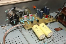
i make on veroboard will take picture.
adding 100uf at output
ac out decrease to 0.098v
ac in 0.143v
next try measuring vbc/vbe each tr
i make on veroboard will take picture.
measuring with load 600r and 100uf at output
sa1837
vbc 1.46v
vbe -0.625
bc337
vbc -0.43
vbe 0.512
sa1837
vbc 1.46v
vbe -0.625
bc337
vbc -0.43
vbe 0.512
This doesn't make sense. Vbc(Q2)=Vce(Q1) in a normally working circuit. Why not here? Broken joint? Also Vce(Q2) adds up to 2V but your voltage drop was 1.4V. Did you make each measurement with the positive probe on the base or did you switch?
- Home
- Amplifiers
- Power Supplies
- Keantoken's CFP cap multiplier