I keep waffling, in simulation all the gain groups act the same so I use the -40 gain group when convenient. The models are from NXP/Phillips and always seemed to be very good quality, so I would not be surprised to find the -40 gain group working as expected in reality.
about how to test it when built  😀
😀
I suppose it works ok if it shows the expected voltage drop of 1.5V ?
ah, the *Troubleshooting* chapter on your website
😀I suppose it works ok if it shows the expected voltage drop of 1.5V ?
ah, the *Troubleshooting* chapter on your website
the SMPS issue brought up here could have another interesting angle/aspect
I have a box loads of those standard wall plug thingies
tried to use one with my guitar effects
but even with this a simple regulated DIY supply sounds better
now Im thinking if the K-multiplier might help to filter the SMPS
but should be easy to check
I have a box loads of those standard wall plug thingies
tried to use one with my guitar effects
but even with this a simple regulated DIY supply sounds better
now Im thinking if the K-multiplier might help to filter the SMPS
but should be easy to check
You could build Tangent's low noise measurement pre-amplifier :
Low Noise Measurement Preamplifier
I have an old 12Mhz scope that goes down to 1mV, and my Fluke is only accurate to 1 or 2mV too, so I'm stuck for precise measurement - so I follow theory and let my ears decide. After all, I do this hobby because I enjoy listening to music as well as making things.
Hello Kean,
Could I replace BD139 with MJE340 or KSE340?
C1 have to be rated 400V?
Could I replace BD139 with MJE340 or KSE340?
C1 have to be rated 400V?
Last edited:
Ok I will order BD139, wich voltage required for C1 82uF? All resistor 1/4W, metal or carbon? LEDs 2V 20mA?
Last edited:
C1 should have the same voltage rating as your reservoir caps. All resistors can be anything 1/4W.
If one wishes to focus on input rejection, performance can be improved without increasing Vf dropout by splitting the 1kohm resistors R2 and R4 into two 499 ohm resistors each, and connecting a capacitor from the R2a/R2b junction to ground (component identifiers refer to schematic on KeanToken's webpage).
KR and Happy New Year!
KR and Happy New Year!
Your suggestion doesn't increase Vf dropout, it turns the reference filter into a second-order one. Increasing Vf may improve PSRR, but I've tried it and it's not much.
Webpage for reference:
The K Multiplier
As far as a better reference filter (R2/C1) I have considered this option before. Input RF leaking through the RF filter depends on the inductance of C1 to ground. Let's say its 22nH, one inch.
For the PSRR to be worse than the Kmultiplier at 100KHz, which is at max say 66db, the inductive reactance has to be 500mX. An inductor with 500mX reactance at 100KHz would be 796nH. 22nH has 14mX, giving a max rejection of over 96db. The Kmultiplier itself is already passing 10 times this much.
ESR of the cap is more of a concern. Using a cap with an ESR of 100mR gives a filter rejection of 80db at max, still swamped by the 66db rejection of the Kmultiplier. However with 500mR, the total Kmultiplier rejection is reduced by half. Most caps at the usual size of C1 have much less ESR than this, but at high voltages you may need caps with higher ESR. At this point current load tends to be reduced so I increase R2 to 10k at the expense of an extra .5V drop.
A much more effective way to improve PSRR is to put an RC filter in front of the Kmultiplier. Unfortunately this increases voltage drop and DC output impedance, unless you take the reference input to before the RC, in which case you probably will need jcarr's suggestion so the the input filter doesn't ruin the fun.
If anyone wants to try it, I'll be interested to hear your results. The Kmultiplier's main draw is its PSRR/Vf ratio, but if you have Vf to spare it's a good idea.
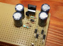
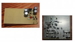
I use a PCB covered in masking tape. I cut and lift away the tape in spots around the circuit for ground connections and to solder wires to with which I clip or anchor components to the board. This gives me an effective ground plane prototype.
This gives me an effective ground plane prototype.
I like the ground plane idea, in general ... but your K-multiplier only has one single ground connection 😉
I know. 😀
And the big caps and things can't get close enough to any ground plane to make a difference. Just talking to myself I guess. >_>
And the big caps and things can't get close enough to any ground plane to make a difference. Just talking to myself I guess. >_>
How about a lc for rf before your K-multiplier . Did you try the bd140 on the negative rail as a k-multiplier ?
To me this looks like a very good stage isolator with little overhead . Well done . Using this for each stage and your low current for the front end would provide freedom in circuit chooses not able to be used because of very poor PSRR other wise. Interesting.
To me this looks like a very good stage isolator with little overhead . Well done . Using this for each stage and your low current for the front end would provide freedom in circuit chooses not able to be used because of very poor PSRR other wise. Interesting.
- Home
- Amplifiers
- Power Supplies
- Keantoken's CFP cap multiplier