Kean, in your schematic the BC327/337 is noted to specificly be the *25* type ?
It refers to the hfe, which you can find on the datasheets, just like 546b 546c etc. If only they used a unified system eh ?
yes, I noticed it....the DC durrent gain
ehh.....since its current and not voltage...is it a driver/transconductance/bias 'figure' ?
ehh.....since its current and not voltage...is it a driver/transconductance/bias 'figure' ?
It's the change in current between collector-emitter due to a change in voltage between base-emitter. Tickle the base and see how much it laughs. Or something like that ;-)
That schematic is OK Merlin
I specify the 25 gain group because that's what I tested and know to work. I haven't tested other gain groups and don't know how behavior changes across gain groups, if at all.
I specify the 25 gain group because that's what I tested and know to work. I haven't tested other gain groups and don't know how behavior changes across gain groups, if at all.
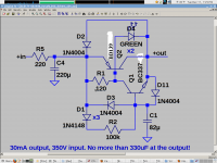
I would say 350V is the max input voltage. It can go as low as you want, but there is not much point in using it below tube voltages.
Hi
I am curious about the schematic Merlin posted - he has used an RC filter with quite a high R (220) - won't that affect the source impedance and hence the overall impedance of the circuit ? Or does the kmultiplier completely negate this ?
I'm also curious to know how to change this kmultiplier for very low currents, say 10mA ? Would it be enough to simply change the bias resistor R1 to a higher value ? I understand this would operate Q2 at less than its optimum current so the circuit would slightly less effective ?
Many thanks for helping me understand...
Tom
Last edited:
The RC is already in Merlin's supply. As it happens, it needs to be there to limit inrush through the Kmultiplier. I'll bet it would be in his supply whether or not my Kmultiplier was with it, so I see it as no consequence. Since the Kmultiplier tracks the input voltage, at DC the Kmultiplier output impedance will be only slightly higher than 220R. But this is with a 10 second delay or so, so it's not much different from having 20 220uF caps after the 220R instead. Except the Kmultiplier rejects RFI like a gyrator instead of shunting it to ground.
At low currents the value of R1 needs to be increased. You want to have the optimal value. The optimal value depends on the Iq of the output as this determines its current gain. The easiest way is to open up the simulator and test a range of values; SPICE models are usually sufficient for this.
At low currents the value of R1 needs to be increased. You want to have the optimal value. The optimal value depends on the Iq of the output as this determines its current gain. The easiest way is to open up the simulator and test a range of values; SPICE models are usually sufficient for this.
Hi
Thanks yet again 🙂
Do you have an LT Spice sim you will share ? If not, or if it is just easier, then for the MJE+BC327, what is the best value of R1 for a 15mA load at 20V DC and 120mV ripple, into 470uF ? (input capacitance of the Kubota regulator I'm using)
That's my last question, honestly ;-)
You should get a medal for helpfulness !
Last edited:

I would say 350V is the max input voltage. It can go as low as you want, but there is not much point in using it below tube voltages.
Could I use with 347 Vin or is very near maximum input voltage?
- Home
- Amplifiers
- Power Supplies
- Keantoken's CFP cap multiplier