Good catch. The input C grounds form a big transmission loop for rectifier pulses. The ground plane would not help with audio frequency rectifier harmonics. Trafo CT should be joined at the terminal blocks and then go to star ground.
thanks Andrew /Keantoken,
Yes, it was the sch. that mislead. Its should be similar to the LM317/337 that I did a while ago.
I am getting some boards made for myself and for anyone who is interested, if I may have Keantoken's permission.
regards
Prasi
Yes, it was the sch. that mislead. Its should be similar to the LM317/337 that I did a while ago.
I am getting some boards made for myself and for anyone who is interested, if I may have Keantoken's permission.
regards
Prasi
Attachments
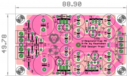
That layout is wrong.
The Centre tap (CT) goes to the junction between the first two smoothing capacitors.
The Centre tap (CT) goes to the junction between the first two smoothing capacitors.
Can someone please explain whether it is better to have a regulator before, or after the K-multiplier? Up to now, I have used the K-multiplier before the regulator, in order to make life more easy when regulating.
That makes the most sense, but there is one exception. The high inductance of chip regulators can cause noise peaks and resonances in the audio spectrum. The question is whether this is more audible than .02-.1 ohm output resistance of the KM.
Jeez, Andrew - the layout is wrong - God has spoken - you're sent down for 20 years - you've failed - you're out!
Perhaps you could express your alterations in a more positive, diyAudio way - simply indicate where he might be able to improve the design, in your opinion, to achieve a better result - it called 'encouragement'.
Now, I might be mistaken but the 78** and 79** regs don't offer a uniform impedance across the freq and power range and also aren't low noise across the same range either, if I remember correctly, yes?
For an amplifier like the HPA-1, this way is (IMO, again) a preferable alternative even if the figures indicate otherwise - some headphone amps do use regulators last with good results, but I find there's a better sound with the C-Mx and K-Mx on the output -
Like a lot of things to do with headamps/phones, you have to try it out to find which one suits your 'taste'
You'll note that there has been no/little mention of capacitor selection here yet - that'll produce some prejudices, no doubt - early days ...
That layout is wrong.
The Centre tap (CT) goes to the junction between the first two smoothing capacitors.
I think I need my sleep. doing two layouts (this PSU on one side and a 500W subwoofer amp on the other ) simultaneously I seem to be making lot of errors.
forgot C1+ existed😱.
Oh, got it. The names c1+ and c1+1 although location is correct on sch , are exchanged on the layout on the positive rail.
A small break always helps.
A small break always helps.
Prasi,
your schematic is going to mislead you into making connections in the wrong places.
The centre tap of the transformer must connect to the junction between C1+ and C1-
................
Good catch. The input C grounds form a big transmission loop for rectifier pulses..................
thanks Andrew /Keantoken,
Yes, it was the sch. that mislead. Its should be similar to the LM317/337 that I did a while ago.
.................
That layout is wrong.
The Centre tap (CT) goes to the junction between the first two smoothing capacitors.
I did !Jeez, Andrew - the layout is wrong - God has spoken - you're sent down for 20 years - you've failed - you're out!
Perhaps you could express your alterations in a more positive, diyAudio way - simply indicate where he might be able to improve the design, in your opinion, to achieve a better result - it called 'encouragement'.....................
both Prasi and KeanT acknowledged that the schematic is misleading. In that first post I described that the CT must go to the first smoothing capacitors (named C1+ & C1-). KeanT then goes on to describe the problems as aerial loops emitting EMI.
Last edited:
Coming to jameshillj's question,
which would work better in the upstream of Keantoken's K-Mult here (just opinions mind you)
1. LM78XX/79XX
2. LM317/337
3. none of the above but something thats entirely made of discrete components like Apex class-A pre-amp PSU?
4. shunt regulators?
May be a bit late to ask the question, as I have too far progressed in layout.
Try this.
Can't get 2SA1930 or TTA004B could you give an alternative?
TIA
Felipe
Attachments
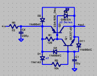
Try the 2SC4883A/A1859A if you can get them. If not see if you can find other 1A+ transistors to try, and verify performance by measuring input and output ripple.
In your version the voltage drop from emitter to collector of Q2 should be about the same, around 1.8V. Maybe a bit more. Voltage drop added by R5 is determined by load current. IE 10mA*82R=0.82V.
- Home
- Amplifiers
- Power Supplies
- Keantoken's CFP cap multiplier