When Ken Peter and I experimented with K-tubes a few years back, we had better luckwhen the driver diameter was approximately the same size as the tube diameter
I'd love to see some measurements if you saved 'em.
what drivers were you using? A specific mix of parameters are required if you're loading the driver with a compression ratio higher than 1:1. That's why I'll start with the JBL 2123 in the bass K-tube--it has a fine track record as a bass horn driver with higher compression ratios, like the ~4:1 I'll be using.
The problem I anticipate with larger diameter K-tubes is that, in the higher end of the passband, if the wavelength shrinks to a significant fraction of the tube diameter, it "sees" less of the tube, acoustically speaking, and starts to beam straight down the axis, and directivity collapses. Higher up, cross-pipe modes develop, adding notches to the response.
Last edited:
I've got one Clothespin - its 9.75"ID, 10.25"OD and 27" long to the two "tips"
Thanks for the info, Fred.
Just looking at those dimensions, I'd expect the Clothespin to begin to really load the driver somewhere above 120Hz. Loading would be tapering off at ~675Hz as the half wavelength becomes smaller than the interior diameter, and collapsing directivity begins to compensate for diminishing power response.
Do you know what its design passband was supposed to be?
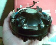
I just took delivery of an interesting pair of midrange compression drivers that I'll add to the mix for testing on K-tubes. They are San Ming SD-210RX drivers (X indicates throatless), intended for use in sirens and paging horns. Their magnets are good-size slugs of neodymium, and they have phenolic diaphragms. I can't find a spec for voice coil diameter, but it's likely somewhere between 2.6" and 2.75".
WT3 shows a free-air Fs of ~400Hz. A plane-wave tube measurement of this model appears in promotional material for the Plus-One Engineering SD4370 (another driver I'd like to test). It is the blue curve.
Judging by appearances, these siren drivers and others like them (including old Klipsch midranges) are direct decedents of the venerable Western Electric 555, sharing the same magnet-behind-diaphragm architecture and single-slit phase plugs.
I'm interested to see how these perform. I hope to commence testing within a month, after a big push at work followed by a vacation cruise. 🙂
Attachments

Last edited:
List of midrange drivers I currently have on hand to test on 1" or 2" dia. K-tubes:
Dynaudio D54AF
Community M200
JBL 2485J
EV DH1A (not really a mid driver, but I'll try it anyway)
Atlas PD-4V
Selenium D250-X
San Ming SD-210RX
Midrange drivers I want to get my grubby little hands on to test:
Plus-One Engineering SD4370
Altec 290
Atlas AS100N
Atlas PD-5VH
Atlas SD-370A
BMS 459*-mid
Any recommendations?
hey Bill F - see this lovely yet? gotta $12.90 10" on the big K-tube
S.N.A.C.K.
An externally hosted image should be here but it was not working when we last tested it.
S.N.A.C.K.
hey Bill F - see this lovely yet? gotta $12.90 10" on the big K-tube
An externally hosted image should be here but it was not working when we last tested it.
S.N.A.C.K.
Freddi: I see that you have got out all your guns. Best regards Moray James.
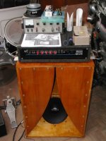
I found 2" PVC Ktube and Klothespin effective as phase plugs when
held a quarter inch from the Dustcap of a 12" speaker. But I did not
find that diameter to sound good with any compression driver.
These are rather short as shown, but started long, and were cut down
to find the optimum length. I suspect optimum would have been "0",
but I got tired of the experiment, once I could see where it was going.
Attachments
if you look carefully under the picture above you'll see a link - that's not my toy. I have rear loaded smaller pipes and also front loaded - like Silvercore featured with a Lowther -K-coupler on top of a La Scala clone.
here's a de-whizzered FE164 in a rear load - there was no damping material in the tube.
its probably good to investigate Karlson's asymmetric projector- when using a coax, an extended K-tube (like Farber Acoustics) can be used to remove the HF from the chamber's influence.
here's a de-whizzered FE164 in a rear load - there was no damping material in the tube.
An externally hosted image should be here but it was not working when we last tested it.
its probably good to investigate Karlson's asymmetric projector- when using a coax, an extended K-tube (like Farber Acoustics) can be used to remove the HF from the chamber's influence.
re: Karlson's asymmetric projector (aka "klam") here's some notes posted to Job Ulfman's Karlson Speaker Forum from Lars Moseholm who took plots of spl out to 25 meters on an 8" klam which was manufactured by Alan Weiss
*****
Alan's "Patio" speaker loaded with B20/BOFU which would typically mount on a tripod (also sold for house of worship)
LAR’S REPORT ON WEISS PS2000 K-COUPLER
"-Dear Group,
The PS2000 taper rate is 4.23 1/m corresponding to a frequency cut-off 116 Hz.
A horn for this rate suitable to the dimensions of the PS2000 (throat area St=500 cm^2 [77.5 in^2] and length L=30 cm [11.8 in]) would have a mouth area Sm=1760 cm^2 [273 in^2].
For comparizon the area of the tapered opening of the PS2000 is 256 cm^2 [40 in^2]
and the area of the terminating PS2000 'mouth' is Smk=90 cm^2 [14 in^2].
The horn radiates sound determined by the mouth real impedance.
The PS2000 radiates through the real impedance of the tapered opening, and the end area Smk (nose area). If the horn is short, or if a lot of energy is left behind in the wave front before it reaches the nose area in the K-couper, a lot of reflections take place.
This is well known to all of you. Some more information on the PS2000 speaker.
The mechanical resistance of the driver motor is 5.7 N*sec/m. The mechanical resistance of the driver suspension losses is 1.6 N*sec/m. The mechanical resistance of the back chamber load (vol. = 5 liters)
on the speaker is 1.65 N*sec/m.
Those resistances determine the SPL together with the real mechanical impedance of the throat.
The optimal (horn) throat area for max. efficiency of the system is 85 cm^2 [13 in^2] which would give a max. SPL 1W/1m close to 107 dB. The actual PS2000 St is 4 times larger, lowering the SPL.
Based on well known horn equations I estimated the complex imput impedance of the above horn.
Then I applied the Poppe equations (which also are the well known horn equations if there is no loss through the tapered opening), but adjusted for loss - and this is where the transmission line theory comes in handy - , and from that I also estimated the throat complex impedance of the PS2000.
I had at this point to assume that the K-coupler was a tube
(I have not worked out the clam design yet - so it is a first approximation).
It should also be noted that the PS2000 K-coupler is very short. For all energy to emit through the tapered opening the length should be about 90 cm [34 in] for that specific taper rate, so one would expect a lot of reflections.
I found the k_coupler acoustical characteric capacitance to be Co=9.9*10-^8 m^5/N
and inductance Lo=6.6 N*s^2/m^5.
Due to the tilt of the panel (and square form) Co would decrease and Lo would increase compared
to the tube form assumed. The overall effect would be a relative increase in
throat impedance in the clam type box compared to a tube. At the same time more energy would be forced
out through the tapered opening.
The resulting SPL for the horn as well as the PS2000 was about 103-105 dB.
The cut-off for the horn was the assumd 116 Hz, however, the cut-off for the K-coupler
was - as expected - shifted upwards to about 200 Hz.
I clearly found a broad lower K-coupler resonance centered about 400 Hz (100 Hz above measured,first approximation) and the upper peaks and dips. Also the plots did not show the on-axis response below the cut-off where the speaker may behave more like a closed box design.
In conclusion: Yes, the PS2000 K-coupler has some significant horn characteristics, and no, it is not optimized.
We only begin to understand the theory, however, we have some rough models to play around with.
I may have made a lot of errors! However, I have scaned the plots and will send them together with the contour plot to anybody interested (Fred and Carl have asked).
I think can get them through the (local) fire-wall by know.
Take care! Lars"
Consider the Karlson designed klam for Jess Oliver - under the AP100 label, they were installed into Radio City
Music Hall. I'd like to replicate this speaker and believe it ran an Altec 421 plus a K-tube tweeter.
*****
Alan's "Patio" speaker loaded with B20/BOFU which would typically mount on a tripod (also sold for house of worship)
An externally hosted image should be here but it was not working when we last tested it.
LAR’S REPORT ON WEISS PS2000 K-COUPLER
"-Dear Group,
The PS2000 taper rate is 4.23 1/m corresponding to a frequency cut-off 116 Hz.
A horn for this rate suitable to the dimensions of the PS2000 (throat area St=500 cm^2 [77.5 in^2] and length L=30 cm [11.8 in]) would have a mouth area Sm=1760 cm^2 [273 in^2].
For comparizon the area of the tapered opening of the PS2000 is 256 cm^2 [40 in^2]
and the area of the terminating PS2000 'mouth' is Smk=90 cm^2 [14 in^2].
The horn radiates sound determined by the mouth real impedance.
The PS2000 radiates through the real impedance of the tapered opening, and the end area Smk (nose area). If the horn is short, or if a lot of energy is left behind in the wave front before it reaches the nose area in the K-couper, a lot of reflections take place.
This is well known to all of you. Some more information on the PS2000 speaker.
The mechanical resistance of the driver motor is 5.7 N*sec/m. The mechanical resistance of the driver suspension losses is 1.6 N*sec/m. The mechanical resistance of the back chamber load (vol. = 5 liters)
on the speaker is 1.65 N*sec/m.
Those resistances determine the SPL together with the real mechanical impedance of the throat.
The optimal (horn) throat area for max. efficiency of the system is 85 cm^2 [13 in^2] which would give a max. SPL 1W/1m close to 107 dB. The actual PS2000 St is 4 times larger, lowering the SPL.
Based on well known horn equations I estimated the complex imput impedance of the above horn.
Then I applied the Poppe equations (which also are the well known horn equations if there is no loss through the tapered opening), but adjusted for loss - and this is where the transmission line theory comes in handy - , and from that I also estimated the throat complex impedance of the PS2000.
I had at this point to assume that the K-coupler was a tube
(I have not worked out the clam design yet - so it is a first approximation).
It should also be noted that the PS2000 K-coupler is very short. For all energy to emit through the tapered opening the length should be about 90 cm [34 in] for that specific taper rate, so one would expect a lot of reflections.
I found the k_coupler acoustical characteric capacitance to be Co=9.9*10-^8 m^5/N
and inductance Lo=6.6 N*s^2/m^5.
Due to the tilt of the panel (and square form) Co would decrease and Lo would increase compared
to the tube form assumed. The overall effect would be a relative increase in
throat impedance in the clam type box compared to a tube. At the same time more energy would be forced
out through the tapered opening.
The resulting SPL for the horn as well as the PS2000 was about 103-105 dB.
The cut-off for the horn was the assumd 116 Hz, however, the cut-off for the K-coupler
was - as expected - shifted upwards to about 200 Hz.
I clearly found a broad lower K-coupler resonance centered about 400 Hz (100 Hz above measured,first approximation) and the upper peaks and dips. Also the plots did not show the on-axis response below the cut-off where the speaker may behave more like a closed box design.
In conclusion: Yes, the PS2000 K-coupler has some significant horn characteristics, and no, it is not optimized.
We only begin to understand the theory, however, we have some rough models to play around with.
I may have made a lot of errors! However, I have scaned the plots and will send them together with the contour plot to anybody interested (Fred and Carl have asked).
I think can get them through the (local) fire-wall by know.
Take care! Lars"
Consider the Karlson designed klam for Jess Oliver - under the AP100 label, they were installed into Radio City
Music Hall. I'd like to replicate this speaker and believe it ran an Altec 421 plus a K-tube tweeter.
An externally hosted image should be here but it was not working when we last tested it.
Last edited:
It should also be noted that the PS2000 K-coupler is very short. For all energy to emit through the tapered opening the length should be about 90 cm [34 in] for that specific taper rate, so one would expect a lot of reflections.
This part caught my eye. He seems to be referring to a formula for slot length based on taper rate?
I don't know how that might apply to my (not tapered) Karlson tubes, but I have a guesstimated hypothesis that slot length should be at least a quarter wavelength at lower cutoff to prevent reflections back up the tube.
Another hunch of mine is that keeping k-tube interior diameter smaller than half a wavelength (ideally < 1/4 WL?) at upper cutoff helps those traveling pressure waves expend their energy through the slot instead of carrying it to the end of the tube.
I found 2" PVC Ktube and Klothespin effective as phase plugs when
held a quarter inch from the Dustcap of a 12" speaker. But I did not
find that diameter to sound good with any compression driver.
These are rather short as shown, but started long, and were cut down
to find the optimum length. I suspect optimum would have been "0",
but I got tired of the experiment, once I could see where it was going.
(Sorry for repeating myself here) but I'm suspicious that any 2" dia. K-tube should be lowpassed somewhere before its half wavelength--3.3kHz. Sure, it will pass higher frequencies, especially down its axis, but above that, directivity will probably collapse fast, and the frequency response of room reflections will droop and make it sound odd.
On the low end, I'm guessing it's important to have a long enough slot to prevent in-tube standing waves.
Last edited:
Nice project Bill, I hadn't caught this thread yet. Allow me to share a bit of experience with the 1" TPC "The Tube" which I own a pair of.
I was reading how Earl Geddes says that any compression driver on a horn or waveguide will exhibit a minimum of two impedance peaks at the lower part of its bandwidth and that more peaks in the Z profile are indicative of a bad horn/WG. I think that the Z profile of a 5.3” long 1” diameter K-tube ala Transylvania Power Company looks very good if going by the above. See freddy's earlier graph with BM-D440 driver. The long-stub tube does introduce such additional Z peaks though.
Here is the response for BMS 4550 on the TPC “The Tube”, where I have an 8ohm swamping resistor across the driver and a 2nd order network comprised of a 6.8µF cap and a 1.5mH inductor:
The above is simply the same trace three times with offset and different levels of smoothing.
IMO, the K-tube transforms impedance as you described earlier, but has an effective mouth area larger than the half-ellipse cutout area. If we set 1kHz as the lower end of its pass-band, as this is where we find the two impedance peaks, (1/3*lambda)^2 then suggests a mouth area of 131cm^2. The cutout area is more like 24cm^2, so re-arranging the formula, we’d get ~2.3kHz. In practice, it seems the tube should be crossed-over at 1.5kHz or above, depending on driver capability. The BMS 4550 will play down to 800Hz on it though, where response falls and distortion rises fast, but it's better to stick to ~1.5kHz.
IMO K-Tube treble does sound very clean and clear. There is more HF output when “looking” down the tube’s axis, but it seems better dispersion is attained when going up to ~30° down the slot, so the angle would be driver-dependent to some extent.
IG
I was reading how Earl Geddes says that any compression driver on a horn or waveguide will exhibit a minimum of two impedance peaks at the lower part of its bandwidth and that more peaks in the Z profile are indicative of a bad horn/WG. I think that the Z profile of a 5.3” long 1” diameter K-tube ala Transylvania Power Company looks very good if going by the above. See freddy's earlier graph with BM-D440 driver. The long-stub tube does introduce such additional Z peaks though.
Here is the response for BMS 4550 on the TPC “The Tube”, where I have an 8ohm swamping resistor across the driver and a 2nd order network comprised of a 6.8µF cap and a 1.5mH inductor:
An externally hosted image should be here but it was not working when we last tested it.
The above is simply the same trace three times with offset and different levels of smoothing.
IMO, the K-tube transforms impedance as you described earlier, but has an effective mouth area larger than the half-ellipse cutout area. If we set 1kHz as the lower end of its pass-band, as this is where we find the two impedance peaks, (1/3*lambda)^2 then suggests a mouth area of 131cm^2. The cutout area is more like 24cm^2, so re-arranging the formula, we’d get ~2.3kHz. In practice, it seems the tube should be crossed-over at 1.5kHz or above, depending on driver capability. The BMS 4550 will play down to 800Hz on it though, where response falls and distortion rises fast, but it's better to stick to ~1.5kHz.
IMO K-Tube treble does sound very clean and clear. There is more HF output when “looking” down the tube’s axis, but it seems better dispersion is attained when going up to ~30° down the slot, so the angle would be driver-dependent to some extent.
IG
Excellent info! Thx IG! What were your smoothing settings?
From top to bottom traces, 1/3, 1/6 and 1/12, the latter is usually pretty revealing I find that going with higher resolutions is not much more useful, mostly because of our own ears/brain smoothing function.
This is the best measurement I've made so far and it also sounds very good. I'm not at 30° down the slot, but not on the tube's axis either, maybe 10°.
IG
Last edited:
Yeah. for 1/12 octave, that's a pretty clean trace alright.
Have you made any qualitative or quantitative comparisons with horns/waveguides?
Also, any off-axis measurements? Judging by the shape of the upper end of the curve, it must be trading some dispersion for flatness, like a horn would. Moving ahead with my plan to limit tube diameter to quarter or half lambda at upper cutoff, I expect to see more upper end droop, like CD waveguides have.
Last edited:
Only comparisons I've made with other horns have been with a ~3kHz 90° conical WG with OS-like throat and a ~1.6kHz mini Smith horn, both DIY creations, so nothing like you might have "exactly" heard. Still, I can say I like The Tube best. Here is a copy from a thread on another forum, where I compared and measured all three, with three different CD's:
--------------------------------
Here are the CD's and WG's under test:
All tests were done with the ~1.5khz PLLXO, no correction on any WG or CD. All graphs smoothed to 1/6 octave.
Selenium D220Ti mounted to test the Smith's horizontal dispersion:
Blue trace = 0°
Red trace = 30°
Green trace = 50° or the sidewall "limit" for its 100° arc
Vertical dispersion:
Blue trace = 0°
Red trace = ~30° below plane
Green trace = ~30° above plane
I'd say it does quite well at dispersing and confirms my previous "no hot-spot" feel. I also felt the top was rolled-off; it almost exhibits that CD drop-off although I'm pretty certain it cannot be this. Nevertheless, a small series cap could flatten this. It might actually sound very balanced as is in my harsh living room on harsh modern recordings. 🙂
Now here's the BMS 4550 measure on all three WG's:
Blue trace = Smith
Red trace = Woodhorn
Green trace = K-Tube
Last comparison, all three CD's measured on the K-Tube:
Blue trace = BMS 4550
Red trace = Selenium D220Ti
Green trace = P.Audio BM-D440
Of all three WG's the K-Tube measures best stock, with no comp network or physical tweaks.
Listening to D220Ti stereo on the Smiths now, sound pretty good. With the HF drop-off, it kinda sounds like a large fullrange, but without the beaminess.
--------------------------------
IG
--------------------------------
Here are the CD's and WG's under test:
An externally hosted image should be here but it was not working when we last tested it.
All tests were done with the ~1.5khz PLLXO, no correction on any WG or CD. All graphs smoothed to 1/6 octave.
Selenium D220Ti mounted to test the Smith's horizontal dispersion:
Blue trace = 0°
Red trace = 30°
Green trace = 50° or the sidewall "limit" for its 100° arc
An externally hosted image should be here but it was not working when we last tested it.
Vertical dispersion:
Blue trace = 0°
Red trace = ~30° below plane
Green trace = ~30° above plane
An externally hosted image should be here but it was not working when we last tested it.
I'd say it does quite well at dispersing and confirms my previous "no hot-spot" feel. I also felt the top was rolled-off; it almost exhibits that CD drop-off although I'm pretty certain it cannot be this. Nevertheless, a small series cap could flatten this. It might actually sound very balanced as is in my harsh living room on harsh modern recordings. 🙂
Now here's the BMS 4550 measure on all three WG's:
Blue trace = Smith
Red trace = Woodhorn
Green trace = K-Tube
An externally hosted image should be here but it was not working when we last tested it.
Last comparison, all three CD's measured on the K-Tube:
Blue trace = BMS 4550
Red trace = Selenium D220Ti
Green trace = P.Audio BM-D440
An externally hosted image should be here but it was not working when we last tested it.
Of all three WG's the K-Tube measures best stock, with no comp network or physical tweaks.
Listening to D220Ti stereo on the Smiths now, sound pretty good. With the HF drop-off, it kinda sounds like a large fullrange, but without the beaminess.
--------------------------------
IG
Have you caught this thread over at the Full-range forum of this website?
http://www.diyaudio.com/forums/full-range/210966-widerange-dipole-karlson-couplers.html
The poster is working on dipole midrange-format K-tubes, maybe there could be something of interest for your project.
IG
http://www.diyaudio.com/forums/full-range/210966-widerange-dipole-karlson-couplers.html
The poster is working on dipole midrange-format K-tubes, maybe there could be something of interest for your project.
IG
- Status
- Not open for further replies.
- Home
- Loudspeakers
- Multi-Way
- Karlson Tube 3-way Koncept