For inspection/understanding, perhaps the TK6 is most valuable of all, then... Thank you again for the data and taking time to post.
I built it as much to have something to mess with as to have a finished speaker I can use, assuming I can get it to play in a satisfactory manner. I'd prefer a pro-style midbass ultimately though; the 6FE100 might have done well if only it measured to published specs.
Here are three tubes I've built lately for the purpose of testing and perhaps using one on a mono speaker if satisfactory.

The two elliptical tubes are schedule 80 PVC, one has a this and rigid cardboard V-slot. The red & black tube is cardstock with fiberglass tape and PVA glue. It's 5.7" long like the TPC Tube.
I took some measurements on all of these and will share that here. All of the measurements were taken 24" away, with just under 4ft elevation.
I'll first post responses for the TPC clone mounted on a BMS 4540ND. Impedance first, naked driver vs with tube.

I measured on-axis, lateral 23deg and 45deg. I measured three tilt positions for each; 0-tilt is horizontal, 1-tilt is ~30deg up from horizontal and 2-tilt 45deg.
0 degrees, all three tilt angles:

23 degrees, all three tilt angles:

45 degrees, all three tilt angles:

I don't know if I did this right, but here is a weighed average approximating the power response:

The two elliptical tubes are schedule 80 PVC, one has a this and rigid cardboard V-slot. The red & black tube is cardstock with fiberglass tape and PVA glue. It's 5.7" long like the TPC Tube.
I took some measurements on all of these and will share that here. All of the measurements were taken 24" away, with just under 4ft elevation.
I'll first post responses for the TPC clone mounted on a BMS 4540ND. Impedance first, naked driver vs with tube.
I measured on-axis, lateral 23deg and 45deg. I measured three tilt positions for each; 0-tilt is horizontal, 1-tilt is ~30deg up from horizontal and 2-tilt 45deg.
0 degrees, all three tilt angles:
23 degrees, all three tilt angles:
45 degrees, all three tilt angles:
I don't know if I did this right, but here is a weighed average approximating the power response:
Last edited:
Here is the same data for the TPC clone, this time mounted on APT50. The only difference is 4 tilt levels, this time roughly 0deg (horizontal), ~15deg, ~30deg and ~45deg.
Impedance:

0 degrees, all four tilt angles:

23 degrees, all four tilt angles:

45 degrees, all four tilt angles:

Weighed average power response approximation:

Impedance:
0 degrees, all four tilt angles:
23 degrees, all four tilt angles:
45 degrees, all four tilt angles:
Weighed average power response approximation:
Last edited:
Here is the same data for the elliptical tube mounted on APT50.
Impedance:

0 degrees, all four tilt angles:

23 degrees, all four tilt angles:

45 degrees, all four tilt angles:

Weighed average power response approximation:

Impedance:
0 degrees, all four tilt angles:
23 degrees, all four tilt angles:
45 degrees, all four tilt angles:
Weighed average power response approximation:
Last edited:
Here is the same data for the V-slot elliptical mounted on APT50.
Impedance:

0 degrees, all four tilt angles:

23 degrees, all four tilt angle:

45 degrees, all four tilt angle:

Weighed average power response approximation:

Impedance:
0 degrees, all four tilt angles:
23 degrees, all four tilt angle:
45 degrees, all four tilt angle:
Weighed average power response approximation:
I'll post comparative responses for different tilt angles for on-axis, 23deg and 45deg off-axis, for the TPC clone on BMS 4540ND, not for the others unless someone really wants the data.
0deg tilt, horizontal tube:

~30deg tilt above horizontal:

~45deg tilt above horizontal:

0deg tilt, horizontal tube:
~30deg tilt above horizontal:
~45deg tilt above horizontal:
I would say your measurements look good. I did some measurements of my printed K-Tube here: https://www.diyaudio.com/community/threads/3d-printed-k-tube-for-1-compression-drivers.344571/
The BMS 4540ND looks much better than the APT50 to properly evaluate the tubes, but I could not get my wonky PVC adapter on it to test the elliptical tubes.
The paper-fiberglass TPC cone does make a pretty decent graph. It is remarkably flat measured straight down the tube, but it's probably not the best position to listen at. From the above data set, I think the best bet might be to equalize the power response, much like a constant directivity horn, and listen slightly off-axis with the tube up ~30deg or so. A small capacitor in the 1.5µF to 2.2µF range might do the trick and flatten the power response down to ~3kHz or so. I've identified two tube positions that I can average and get within 2dB of the "power response" for quickly testing this.
The V-slotted elliptical looks somewhat better than the un-slotted. I should try to get them on the BMS driver for a better look. I would have liked to try a somewhat longer elliptical, but this is the longest I could cut with a handsaw in a custom mitre box.
Last edited:
pelanj,
Re-reading your linked thread, I suppose I agree with your comment on the 40x20 dispersion. It's some very cool 3D print you made there and DonVK's simulations pretty much agree with your and my measurements I would say.
Re-reading your linked thread, I suppose I agree with your comment on the 40x20 dispersion. It's some very cool 3D print you made there and DonVK's simulations pretty much agree with your and my measurements I would say.
As an attempt to equalize the power response I approximated in post #43 for the BMS 4540ND and paper/fiberglass TPC clone, I calculated a 1.8µF capacitor for a kneepoint around 14.6kHz. I didn't have that in my box and did not feel like making one from 3-4 other caps, so simply used my nearest value, a 2.2µF. I took measurement at two select positions that approximate the power response when averaged and did just so, resulting in the below.

Not bad at all, the -2dB shelf above ~13kHz isn't even a bad thing IMO. Finding a slightly off-axis point to listen at with fairly flat FR, perhaps even falling slightly, would be what I would do if setting up for stereo, but I'll be listening to the one for now. The best might be to find the ideal on-axis tilt assuming fairly symmetrical room reflections. Here is what the "straight down the tube" response now looks like with the capacitor:

It's up 10dB from 5kHz to 20kHz instead of quite flat unfiltered, not the best spot to listen at.
Not bad at all, the -2dB shelf above ~13kHz isn't even a bad thing IMO. Finding a slightly off-axis point to listen at with fairly flat FR, perhaps even falling slightly, would be what I would do if setting up for stereo, but I'll be listening to the one for now. The best might be to find the ideal on-axis tilt assuming fairly symmetrical room reflections. Here is what the "straight down the tube" response now looks like with the capacitor:
It's up 10dB from 5kHz to 20kHz instead of quite flat unfiltered, not the best spot to listen at.
I have changed driver yet again in the TK6. This time it's an 8" woofer, Peerless 830869. Fs~34Hz, Qts~0.36, Vas~56L. The TK6 is on the small side of things for this driver, but the medium-low Qts should allow for it.

I have also changed the venting scheme, from four 1.5" holes at the top, to sixteen distributed 0.25" holes. The tuning is in the mid-50ies, as seen on the below comparative impedance response, red is the new scheme, also with a Zobel.

The 16 small holes also add a resistive element as seen on the lowered peaks.
I've measured the frequency response on the previous 4 holes vent, but no yet on the distributed scheme. I will post the comparison when done.
I have also changed the venting scheme, from four 1.5" holes at the top, to sixteen distributed 0.25" holes. The tuning is in the mid-50ies, as seen on the below comparative impedance response, red is the new scheme, also with a Zobel.
The 16 small holes also add a resistive element as seen on the lowered peaks.
I've measured the frequency response on the previous 4 holes vent, but no yet on the distributed scheme. I will post the comparison when done.
Here is a nearslot measurement of the old 4 1.5" holes venting versus 16 0.25" distributed holes.

The same at 25cm.

I'd say it improved the issues in the 200-400Hz region, which I was hoping for.
I've kludged a quick and dirty crossover for the K-Tube on top of this latest iteration of the TK6, meeting around 3kHz. It's the best sound I got out of this box so far. The bass isn't very deep, but it sounds fuller than I'd imagine from the graph, and the midbass is pretty decent. There is much less subjective coloration in the lower midrange than with 6FE100 or dual FF125K, despite not terribly different measurements.
The same at 25cm.
I'd say it improved the issues in the 200-400Hz region, which I was hoping for.
I've kludged a quick and dirty crossover for the K-Tube on top of this latest iteration of the TK6, meeting around 3kHz. It's the best sound I got out of this box so far. The bass isn't very deep, but it sounds fuller than I'd imagine from the graph, and the midbass is pretty decent. There is much less subjective coloration in the lower midrange than with 6FE100 or dual FF125K, despite not terribly different measurements.
all cool and interesting with the EQ-ed tube and 8 inch woofer
FWIW here's a very non-precise take on my "LASE" RN72-1.5 compression driver. Its cheap ($62 shipped)-heavy -13lb, pretty loud, and apparently limited to 5KHz. That said, its good on acoustic guitar, percussion, etc. It could get cumbersome adding a high xover K-tube
I hand held the mic. Pelanj's tubes and various 3D printed K-stuff gifts are beautiful. I don't have a decent camera and wore out from health issues.
Attachments
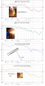
The response is pretty good on that combo IMO. It falls-off smoothly on top. Maybe a 1.5-2.2µF capacitor would equalize it nicely like I did for the rough power response.
I haven't listened to the plain elliptical tube and will likely not, but the V-slot sounds decent and measures better, though different from the K-Tube. I was thinking it'd load the driver at least as well as the K-tube, but it does not seem to be the case. Trade-offs like usual.
DonVK's ABEC models are really cool and in agreement to pelanj's and my own measurements to boot. It's probably the best objective data I've seen on the K-Tube so far.
I might also inquire with a friend about printing a pair of pelanj's tubes. In the meantime, I'm making more paper + fiberglass tape + PVA glue tubes, a pair this time. Will most likely make them to TPC dimensions again. They'll be for my pair of BMS 4540ND so I can listen in stereo. I might try them for a while above the Peerless 830869 in sealed box. Not exactly hi-efficiency, but it's what I have on hand. They'll sub-in for my TD15M while I take care of noise issues in the 4ch amp I use to bi-amp them. Perhaps I was too ambitious cramming a mini-DSP and 2 ICEpower boards inside a small-ish chassis!
I'd like to see a V-slot K for the 3-8" driver range as that might approximate Karlson's AP9C (6"x9") ceiling speaker.
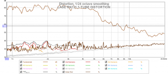
My LASE RN2 1.5" driver looks ok distortion-wise. I might try a PRV since they publish specs.
My LASE RN2 1.5" driver looks ok distortion-wise. I might try a PRV since they publish specs.
Attachments
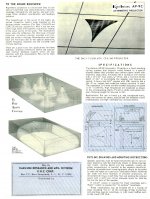
The AP9C's pattern is made to look interesting on the brochure, but the elevated power requirement isn't mentioned anywhere. 😉
Here are the tubes I've been working on.

I decided to go for something longer for a change. 7.5" of slot and 0.5" unslotted base. I figured 1.4142x the standard 5.3" tube, what the heck. Materials are a thick, dense and smooth orange paper found at an arts&crafts store - I'm not sure what the intended purpose is - with 4 helicoidally counter-wrapped layers of fiberglass tape, brushed several times with PVA glue and painted with grey acrylic paint to finish. I'll probably build a simple mounting base for bolt-on compression drivers, to allow using with BMS 4550, and figure out a mounting scheme for the thread-on 4540ND or just buy adapters if I like them enough.
Here are the tubes I've been working on.
I decided to go for something longer for a change. 7.5" of slot and 0.5" unslotted base. I figured 1.4142x the standard 5.3" tube, what the heck. Materials are a thick, dense and smooth orange paper found at an arts&crafts store - I'm not sure what the intended purpose is - with 4 helicoidally counter-wrapped layers of fiberglass tape, brushed several times with PVA glue and painted with grey acrylic paint to finish. I'll probably build a simple mounting base for bolt-on compression drivers, to allow using with BMS 4550, and figure out a mounting scheme for the thread-on 4540ND or just buy adapters if I like them enough.
Those tubes are very pretty ! Do you think TK6 made 4" wider might make a kool "K10"? I'm pretty sure a good K10 with K-tube and 25-100 watts would punch and be impressive with some music - certainkly with drumkit.
I'll disclose that the look of the above K-tubes would make them a nice match for the Volvotreter midbass horns, from which I may have taken a bit of inspiration... 🙂
As mentioned in other recent Karlson threads, but perhaps only anecdotal, I'd make a K10 no more than 12" of internal width and 5" of maximum front chamber depth, that is, from wings to baffle/reflector meeting point. Height I don't know for certain, but 18" to 24" should be OK, perhaps affected by the rear chamber design (BR or TL) which should in turn be tuned somewhat high for ~3dB of gain in the midbass.
As mentioned in other recent Karlson threads, but perhaps only anecdotal, I'd make a K10 no more than 12" of internal width and 5" of maximum front chamber depth, that is, from wings to baffle/reflector meeting point. Height I don't know for certain, but 18" to 24" should be OK, perhaps affected by the rear chamber design (BR or TL) which should in turn be tuned somewhat high for ~3dB of gain in the midbass.
I built bolt-on base plates for the K-Tubes. Here is the BMS 4550 attached on one.

With 4540ND for comparison.

I still have to drill some holes in the lateral extensions for mounting to an eventual stand or baffle.
I was only able to measure the impedance response so as not to be too noisy this late in the evening. Here is the naked 4550, along with 7.5" K-tube mounted.

I measured again, with a 1.5" wide piece of tape blocking the first 1.5" of the slot, where it's narrowest, then again with two for 3" blocked. Graph is zoomed-in 400Hz-4kHz for better legibility.

While I do not have an actual mount for screw-on drivers, I just placed the 4540ND on the 7.5" K-tube, held tight by hand and measured the response.
Here it is compared to the 4540ND on the 5.3" red&black tube shown and measured earlier.

With 4540ND for comparison.
I still have to drill some holes in the lateral extensions for mounting to an eventual stand or baffle.
I was only able to measure the impedance response so as not to be too noisy this late in the evening. Here is the naked 4550, along with 7.5" K-tube mounted.
I measured again, with a 1.5" wide piece of tape blocking the first 1.5" of the slot, where it's narrowest, then again with two for 3" blocked. Graph is zoomed-in 400Hz-4kHz for better legibility.
While I do not have an actual mount for screw-on drivers, I just placed the 4540ND on the 7.5" K-tube, held tight by hand and measured the response.
Here it is compared to the 4540ND on the 5.3" red&black tube shown and measured earlier.
- Home
- Loudspeakers
- Multi-Way
- Karlson "TK6" & K-Tube