GM,
I know about half and quarter wave resonances, but can't seem to equate all peaks/dips to physical dimensions on my cab, while certain dimensions I might expect to have standing waves don't have a measurement 'wart' to go with.
I know about half and quarter wave resonances, but can't seem to equate all peaks/dips to physical dimensions on my cab, while certain dimensions I might expect to have standing waves don't have a measurement 'wart' to go with.
Because it's a tuning 'thing', i.e. a Karlson is a multiple series tuned BP with each 'box' tuning adding another order, so the first one is 4th order since it's vented, add another in series and it's a 6th order, etc., so in summing there will be a 3rd harmonic dip and associated peaks, dips same as if it was a TL, horn. IOW he created a tapered horn folded back on itself, then calculated the average box volume for each 'step' in the flare, using vents to acoustically tie them together.
As for designing to line up with room modes, way past my math skills, patience, so could only measure the room and keep tweaking a design till it lines up with the worst of the modes.
As for designing to line up with room modes, way past my math skills, patience, so could only measure the room and keep tweaking a design till it lines up with the worst of the modes.
Last edited:
I had not really considered further harmonic modes yet, thinking the main modes would be obvious, but there are indeed lots of things going with multiple chambers. I'll look into it some more. I'm also building a smaller and somewhat simpler "XKi", both for fun and as a second data set for comparative purpose. Thanks for the input!
using a damped stub attached to the front chamber should help for some cases.
Tell me more concerning getting a good bandwidth
IMO K15 does pretty well with front chamber tuning around 110-120 as that constitues
a harmonic area for drums and bass while cone excursion and sidebands are lower than with single chamber reflex.
Years back I purchased a Yorkville speaker - it had the LAB15 as driver. Its HD was 20dB worse
than a Sigma18 type thrown into a simple and un-optimized K roughly the same size as K15.
Attachments
Tell me more concerning getting a good bandwidth
Assuming a flat response in the pass-band, I think 3 octaves might be the max one can get at the driver's efficiency; as you raise the gain, the BW will naturally get narrower. 2 or 2.5 octaves isn't bad at all, but getting a uniform response within is key, though I don't mind a bit of upward tilt. I have 3 octaves on the TK6, but a huge peak.
For a while, I assumed some quarter-wave effect was going on in the front chamber, related to its height, and that's the tuning I was using when BP6 modeling. I'm fairly certain I was wrong, but for classic form-factor kouplers, it mostly coincided with the cavity resonance when scaling-down from K15. It "checked-out" with my K12 and SK8, possibly the K5 too IIRC. I think the first few high-aspect koupler builds threw-off my humble model though, when I saw measurements.IMO K15 does pretty well with front chamber tuning around 110-120
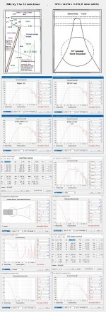
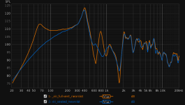
Here`s a bit of (for now) tangential analysis, though I hope to eventually connect it to the points raised in the first post as well as subsequent comments by other members.
Let`s break down the TK6 into stand-alone blocks.
Rear bottom chamber: 10.1 liters with 4x 1.5" holes in 7/16" plywood. Free-air Fb=186Hz.
Rear top chamber: 5.2 liters with 4x 1" holes in 7/16" plywood. Free-air Fb=199Hz.
Lumped rear chamber: 15.3 liters with 4x 1" holes in 7/16" plywood. Free-air Fb=116Hz.
My measured Fb is actually 69Hz, far below the predicted 116Hz. Thus far the front chamber was ignored; it of course created an air-load upon the top vents. Using Hornresp, I modeled the equivalent horn that would get Fb down to what I measure. I used a horn mouth of area approximately that of my K-slot. I then merely adjusted the length until Fb=69Hz. The Hornresp record is also attached.

The horn`s Vb is 2.5 liters, while my front chamber is 6.4 liters. I never looked at its whole volume as being effective anyway, so it somewhat lines up with how I picture it working. The impedance peak magnitude does not match, but I do have two drivers with differing Fs and compliance unfortunately, possibly what created the wiggles on my posted chart in post #1.
This makes my TK6 into a folded BVR, which usually has a PAR expansion vent. I know the K-slot`s two-dimensional expansion is not PAR, but it`s also not a horn. The simpler K-Tube, I look at it as an "anti-horn", as it does not provide a gradual expansion, but a gradual "leakage". There may be a better model for the K-slotted front chamber, but that`s what I came up with for now. If I use a PAR horn in my above HR model, it then needs to be 8.5 liters in volume for the same mouth area to tune to 69Hz. If I use a CON horn, it is now 5 liters for Fb=69Hz. Not too far-fetched. I think something between CON and EXP is closer to reality.
But if I look at the no-wings response, it`s not as if my Fb did shift up to 116Hz, where I would then expect a 5-6dB peak. I did not yet take a no-wings Z measure, but I assume Fb will be up less than 10Hz at best. The high-aspect of the rear chamber and location of the vent in an acute corner likely goes towards lowering the predicted Fb. The four 1" holes are of substantially larger area than the slot I previously had mid-cab for a similar Fb after all.
Let`s break down the TK6 into stand-alone blocks.
Rear bottom chamber: 10.1 liters with 4x 1.5" holes in 7/16" plywood. Free-air Fb=186Hz.
Rear top chamber: 5.2 liters with 4x 1" holes in 7/16" plywood. Free-air Fb=199Hz.
Lumped rear chamber: 15.3 liters with 4x 1" holes in 7/16" plywood. Free-air Fb=116Hz.
My measured Fb is actually 69Hz, far below the predicted 116Hz. Thus far the front chamber was ignored; it of course created an air-load upon the top vents. Using Hornresp, I modeled the equivalent horn that would get Fb down to what I measure. I used a horn mouth of area approximately that of my K-slot. I then merely adjusted the length until Fb=69Hz. The Hornresp record is also attached.
The horn`s Vb is 2.5 liters, while my front chamber is 6.4 liters. I never looked at its whole volume as being effective anyway, so it somewhat lines up with how I picture it working. The impedance peak magnitude does not match, but I do have two drivers with differing Fs and compliance unfortunately, possibly what created the wiggles on my posted chart in post #1.
This makes my TK6 into a folded BVR, which usually has a PAR expansion vent. I know the K-slot`s two-dimensional expansion is not PAR, but it`s also not a horn. The simpler K-Tube, I look at it as an "anti-horn", as it does not provide a gradual expansion, but a gradual "leakage". There may be a better model for the K-slotted front chamber, but that`s what I came up with for now. If I use a PAR horn in my above HR model, it then needs to be 8.5 liters in volume for the same mouth area to tune to 69Hz. If I use a CON horn, it is now 5 liters for Fb=69Hz. Not too far-fetched. I think something between CON and EXP is closer to reality.
But if I look at the no-wings response, it`s not as if my Fb did shift up to 116Hz, where I would then expect a 5-6dB peak. I did not yet take a no-wings Z measure, but I assume Fb will be up less than 10Hz at best. The high-aspect of the rear chamber and location of the vent in an acute corner likely goes towards lowering the predicted Fb. The four 1" holes are of substantially larger area than the slot I previously had mid-cab for a similar Fb after all.
Attachments
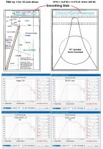
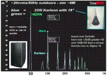
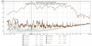
unfortunately for the Karlsonator 6 prototype, all I have for a response curve is it with the L. Cao F6 at 1/6 octave resolution. IIRC driver qts was close to 0.7 and its a bit more sensitive than an Eminence Delta Pro 8 rated "97.3dB".
The prototype was built about 1.5" less deep than GregB's plan as my great friend John Lapaire used whatever scrap material was available. Tuning is ~60Hz.
Damping consisted of some polyfil in the stub and a pad at the cabinet's bottom.
It plays very smooth. The other driver tried was a de-whizzered Fostex FE164. The Fostex had real punch on slapped upright bass and a 166_ would be a solid recommendation if powerful transients are desired.
The other trace in the graph below was from a K8 type and an inexpensive 8" car speaker
with chunky magnet and "bullet phase plug"
FWIW I think its about as close to a "blameless" K "response-wise" as might be seen.
Attachments
unfortunately for the Karlsonator 6 prototype, all I have for a response curve is it with the L. Cao F6 at 1/6 octave resolution. IIRC driver qts was close to 0.7 and its a bit more sensitive than an Eminence Delta Pro 8 rated "97.3dB".
The prototype was built about 1.5" less deep than GregB's plan as my great friend John Lapaire used whatever scrap material was available. Tuning is ~60Hz.
Damping consisted of some polyfil in the stub and a pad at the cabinet's bottom.
It plays very smooth. The other driver tried was a de-whizzered Fostex FE164. The Fostex had real punch on slapped upright bass and a 166_ would be a solid recommendation if powerful transients are desired.
The other trace in the graph below was from a K8 type and an inexpensive 8" car speaker
with chunky magnet and "bullet phase plug"
FWIW I think its about as close to a "blameless" K "response-wise" as might be seen.
Here`s a bit of (for now) tangential analysis, though I hope to eventually connect it to the points raised in the first post as well as subsequent comments by other members.
Let`s break down the TK6 into stand-alone blocks.
Rear bottom chamber: 10.1 liters with 4x 1.5" holes in 7/16" plywood. Free-air Fb=186Hz.
Rear top chamber: 5.2 liters with 4x 1" holes in 7/16" plywood. Free-air Fb=199Hz.
Lumped rear chamber: 15.3 liters with 4x 1" holes in 7/16" plywood. Free-air Fb=116Hz.
My measured Fb is actually 69Hz, far below the predicted 116Hz. Thus far the front chamber was ignored; it of course created an air-load upon the top vents. Using Hornresp, I modeled the equivalent horn that would get Fb down to what I measure. I used a horn mouth of area approximately that of my K-slot. I then merely adjusted the length until Fb=69Hz. The Hornresp record is also attached.
View attachment 1007602
The horn`s Vb is 2.5 liters, while my front chamber is 6.4 liters. I never looked at its whole volume as being effective anyway, so it somewhat lines up with how I picture it working. The impedance peak magnitude does not match, but I do have two drivers with differing Fs and compliance unfortunately, possibly what created the wiggles on my posted chart in post #1.
This makes my TK6 into a folded BVR, which usually has a PAR expansion vent. I know the K-slot`s two-dimensional expansion is not PAR, but it`s also not a horn. The simpler K-Tube, I look at it as an "anti-horn", as it does not provide a gradual expansion, but a gradual "leakage". There may be a better model for the K-slotted front chamber, but that`s what I came up with for now. If I use a PAR horn in my above HR model, it then needs to be 8.5 liters in volume for the same mouth area to tune to 69Hz. If I use a CON horn, it is now 5 liters for Fb=69Hz. Not too far-fetched. I think something between CON and EXP is closer to reality.
But if I look at the no-wings response, it`s not as if my Fb did shift up to 116Hz, where I would then expect a 5-6dB peak. I did not yet take a no-wings Z measure, but I assume Fb will be up less than 10Hz at best. The high-aspect of the rear chamber and location of the vent in an acute corner likely goes towards lowering the predicted Fb. The four 1" holes are of substantially larger area than the slot I previously had mid-cab for a similar Fb after all.
Hi IG81-it would be interesting to see if a front chamber foldback stub is tne most bulk-efficient means for tuning the front chamber"lower"
Indeed a good response on the Karlsonator 6, it lacks a large cavity peak, I'd like to know why though!
It has a similar response to this one:
https://www.diyaudio.com/community/threads/karlson-response-peaks-and-dips.380731/post-6883637
In both cases the flaps don't obstruct much of the speaker cone front, but that's just a guess.
Are the vents always placed at the top of the front cavity?
https://www.diyaudio.com/community/threads/karlson-response-peaks-and-dips.380731/post-6883637
In both cases the flaps don't obstruct much of the speaker cone front, but that's just a guess.
Are the vents always placed at the top of the front cavity?
The vent is usually somewhere in the upper half of the cab. I first built the TK6 with a more central vent, between the two angled panels, then tried the top one my latest measurements reflect.
Attachments

What about the overhead Karlson things in the advertisement, what is the response like for those? They seem closer to the pure K-tube concept.
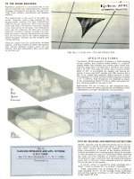
Karlson's AP ("Asymmetric Projector") Clam pattern series arose from Karlson's experiments with the little KR5 Rocket speaker. Karlson made them for 6x9" speakers-one for tripod mount, then the stamped metalAP9C for ceiling installations. Karlson's AP-X with a heavy duty 10 inch guitar type speaker was also marketed by Karlson's friend Jess Oliver as the Oliver Sound Phase III projector. Karlson's AP100 15" model klam was sold by Jess Oliver as "Magna Clam". As I understand the Magna Clam used an Altec 421 15 inch speaker plus a compression driver K-tube
In the "Karlson Compendium" I have Karlson's letter to Marty Poppe (R.I.P.) who wrote 'The K-coupler" paper as a thesi..
John Karlson and assistant Alan Weiss installed a set of AP100 at Radio City Music Hall. Jess and John tried to sell a set to Yankee Stadium but Jess said neither onw of them were good salesmen.
About 20 years ago, Mr. Weiss offered an 8 inch klam which he also called "Rocket" (probably a tribute). At these sizes with the speaker buried back further than with the regular Ultra Fidelity lineup. there are a lot of garbled reflections in the front chamber.
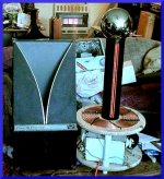
I have a 15" driver klam designed by me and built by great K-friend John Lapaire. It sounds quite good with a 15 inch coaxial and alto with a crude extension from the horn with a K-tube. Theback chamber is sealed and around 2 cubic foot IIRC. That klam could be shortened by removing a few inches of back chamber length to further improve power handling - I think its a keeper.
I built an 18" klam from one sheet of plywood.
Below is a short video of the15 inch klam - plus a sketch of a klam 12 built - my poor health and damage of main house by mice has precluded my return to test and experiment - maybe this coming year.
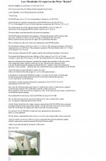
Also - a bit of Lars Moseholms' Weiss Rocket analysis
.
In the "Karlson Compendium" I have Karlson's letter to Marty Poppe (R.I.P.) who wrote 'The K-coupler" paper as a thesi..
John Karlson and assistant Alan Weiss installed a set of AP100 at Radio City Music Hall. Jess and John tried to sell a set to Yankee Stadium but Jess said neither onw of them were good salesmen.
About 20 years ago, Mr. Weiss offered an 8 inch klam which he also called "Rocket" (probably a tribute). At these sizes with the speaker buried back further than with the regular Ultra Fidelity lineup. there are a lot of garbled reflections in the front chamber.
I have a 15" driver klam designed by me and built by great K-friend John Lapaire. It sounds quite good with a 15 inch coaxial and alto with a crude extension from the horn with a K-tube. Theback chamber is sealed and around 2 cubic foot IIRC. That klam could be shortened by removing a few inches of back chamber length to further improve power handling - I think its a keeper.
I built an 18" klam from one sheet of plywood.
Below is a short video of the15 inch klam - plus a sketch of a klam 12 built - my poor health and damage of main house by mice has precluded my return to test and experiment - maybe this coming year.
Also - a bit of Lars Moseholms' Weiss Rocket analysis
.
Attachments
-
 LarsWeiss Rocket 1.jpg312.8 KB · Views: 104
 -
 AP9C ok 1.jpg559 KB · Views: 102
 -
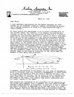 K-LETTER PG 1.jpg482.8 KB · Views: 93
 -
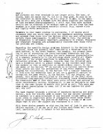 K-LETTER PG 2.jpg481.8 KB · Views: 93
 -
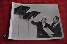 JESS WITH JOHN.jpg95.5 KB · Views: 92
 -
 MAGNA-KLAM AKA AP100.jpg442.6 KB · Views: 104
 -
 AP9C DIMS.jpg8.7 KB · Views: 106
 -
 PHASE 3 PROJECTOR.JPG124.7 KB · Views: 99
Last edited:
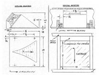
Here's the approximate dimensions of The Karlson -Oliver Phase III projector.which used a 10 inch speaker. A pair were reported to play stereo music to 5000 people. It hd a leay vent formed by a hole in thebaffle and grill cloth over the baffle. A thin sheet of acrylic was glued to thetop plate to reduce high frequency losses (there weren't a lot of highs with its heavy duty 10" guitar speaker but something to consider if a coaxial is used.
Also, I'm pretty much sure if scaled Phase III for a 15 inch speaker that one will replicate Karlson's AP100/Magna Clam.
hey IG8a - sometime make a Weiss mini-klam for 1 inch compression driver. I think it has some merit when used above head level and pointing "down".
Also, I'm pretty much sure if scaled Phase III for a 15 inch speaker that one will replicate Karlson's AP100/Magna Clam.
hey IG8a - sometime make a Weiss mini-klam for 1 inch compression driver. I think it has some merit when used above head level and pointing "down".
Attachments


Here is a Karlson from 2005 that I randomly discovered:
https://www.diyaudio.com/community/threads/diyaudio-full-range-reference-project.46934/post-563006
https://www.diyaudio.com/community/threads/diyaudio-full-range-reference-project.46934/post-563006
That's one of Moray's K-1/4 wave T-lines- Moray is picky so they must be pretty good
hornresp might be able fudge-sim that type
https://www.diyaudio.com/community/...-4-wave-t-line-cabinet-for-fe167e-etc.359976/
hornresp might be able fudge-sim that type
https://www.diyaudio.com/community/...-4-wave-t-line-cabinet-for-fe167e-etc.359976/
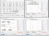
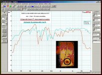
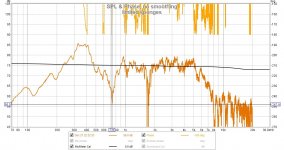
speaking of dips and peaks, these are my first findings on the squat K8 8pl21 midrange module.
I really needs for a usable graph, melamine sponges packed behind the upper half of the wings
I'm terrible with REW right now -forgotten what little I knew -can't remember how to smooth, etc.
A crossover would need to flatten that ~330Hz cavity peak. A stub would probably work. Can a resonator plaeced in a cabinet's rear exert as much nuling as one on the front chamber?
Attachments
Last edited:
- Home
- Loudspeakers
- Full Range
- Karlson response peaks and dips