Here is a truly minimalist amplifier: a total of 4 transistors, and it actually works, it has been built.
I think it would be difficult to make even simpler without seriously compromising something.
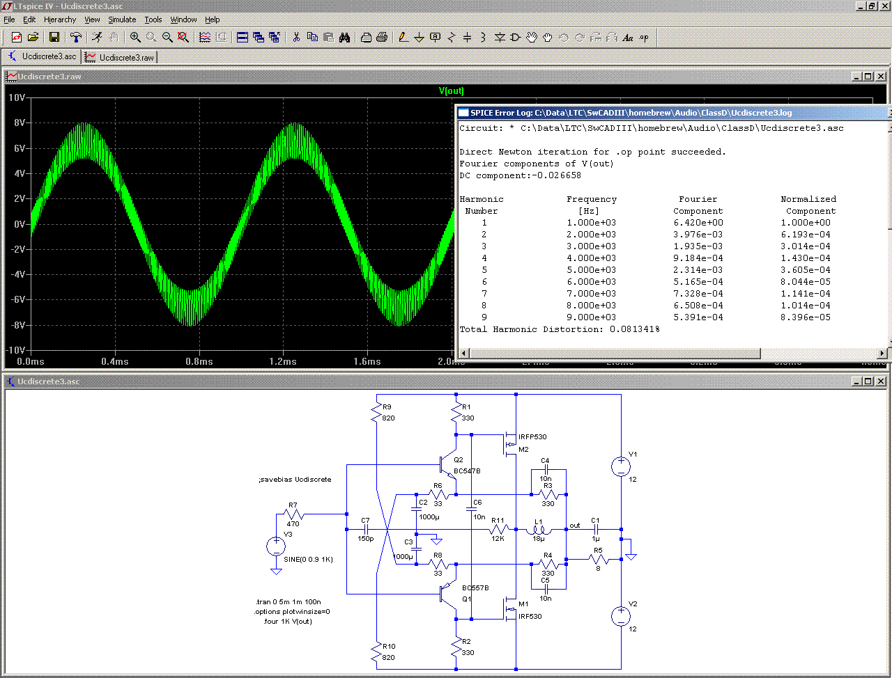
Have fun!!!
I think it would be difficult to make even simpler without seriously compromising something.
Have fun!!!
Brilliant. This renders all other previous ZEN work (and thinking) obsolete.
btw: I think you mislabeled IRF9530 as IRFP530.
btw: I think you mislabeled IRF9530 as IRFP530.
Sorry about that: as there was no IRF9530 in the native library, I simply changed the sex of a IRF530 as a quick fix.btw: I think you mislabeled IRF9530 as IRFP530.
The transistor I used in my prototype was in fact a IRF9630, and I forgot to edit the name after the sim was completed.
I know you did this for fun, but how well does it work?
This is simple enough for even me to build; not that I understand how it functions in the least. Have the parts to do it though, so why not.
This is simple enough for even me to build; not that I understand how it functions in the least. Have the parts to do it though, so why not.
I got to say, this one will be hard not to just try and see, just for the fun of it
did you try it on any other voltages too, I got few supply, that have a bit higher voltage
did you try it on any other voltages too, I got few supply, that have a bit higher voltage
Difficult to tell: other than a dummy load, I tested it on an unboxed 4" speaker.I know you did this for fun, but how well does it work?
In those conditions, it sounded normal....
No I didn't. I tested it on a regulated supply, and with unregulated supplies there would probably be ripple rejection issues.did you try it on any other voltages too, I got few supply, that have a bit higher voltage
It could probably tolerate somewhat higher supplies, but at some point, the gate voltage might become excessive, as this is not controlled in any way.
Up to +/-20V should be safe, but be careful...
Want to try on yourself? Naughty boy!Very cool!
Question: how do you change the sex of an IRF530?
(I mean in LTspice😀)
-E
Open the standard.mos library with a text editor, copy and paste the line of the victim transistor, and edit "nchan" into "pchan", and also edit the component name in recognizable way; when I do this kind of "operation", I add a P or a N somewhere, and I take care not to duplicate any real component.
When it's done, it looks like this:
which is an ideal complement for the IRF530..model IRFP530 VDMOS(pchan Rg=3 Vto=-4 Rd=50m Rs=12m Rb=60m Kp=5 lambda=.01 Cgdmax=1n Cgdmin=.26n Cgs=.2n Cjo=.4n Is=52p mfg=International_Rectifier Vds=100 Ron=160m Qg=26n)
Not very realistic in real life, at least for MOS transistors. For BJT's, it is less of an issue, you can find real components that are almost an ideal match.
I tried only on 8Ω, full power (12V supplies) and the transistors remained cool.nice one elvee. do the outputs heat at 2 ohms playing hard?
Only the 18µH coil was hot, but it was an ordinary iron powder (white yellow) toroid, not quite suited to the ~200KHz switching frequency
😛Actually I've already tried the sim with other complementary pairs, and it works nicely. So I just wanted to reproduce your original.Want to try on yourself? Naughty boy!
Thanks much for the directions, cheers
-E
Edit: I believe the P version should also have Vds changed to -100
Last edited:
any feedback would be hard to add, am I right?
it seems you can only use complementary pairs or you'll get offset, is this corrent?
it seems you can only use complementary pairs or you'll get offset, is this corrent?
any feedback would be hard to add, am I right?
But there is already feedback!!
R3-R6 and R6-R8 set the theoretical closed loop gain to 11, but since the open loop gain is of the same order, the resulting closed loop gain is approximately the half of that.
You could set a lower closed loop gain, this would result in an even better distortion.
Note that with this simple design, you need good quality supplies: the average gate voltage is a direct proportion of the supply voltage, and because of C6 crossing the gates, any noise on the supply rails will appear in the G-S voltages. This requires a good decoupling.
That is when you have monitor too close... then I simulated myself and I've seen it.But there is already feedback!!
R3-R6 and R6-R8 set the theoretical closed loop gain to 11, but since the open loop gain is of the same order, the resulting closed loop gain is approximately the half of that.
You could set a lower closed loop gain, this would result in an even better distortion.
Note that with this simple design, you need good quality supplies: the average gate voltage is a direct proportion of the supply voltage, and because of C6 crossing the gates, any noise on the supply rails will appear in the G-S voltages. This requires a good decoupling.
any reason why not to use higher switching freq?
I changed 150p to 33p or 47p
C7 does not actually set the oscillating frequency, its role is to provide some positive feedback, to make the oscillations clean and strong.
As in other UcD schemes, the frequency is set by C4, C5, the output filter, and other marginal delays in the loop, like the lowpass filtering caused by the MOS input capacitance and resistors R1 and R2.
If you attempt to act on a single element, the performances will decrease because this lowpass will tend to dominate, and will also increase the losses.
You could add follower stages before the MOS transistors, but then it would become a six-transistor UcD, not a 4...
Elvee,
clever little circuit you have tossed our way here .
.
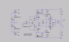
After hours of sim to learn it, here is a version with +-20V rails. Keeping the changes from your original to the minimum to allow fair comparisons:
- limited the gate drive to 8.2V
- tweaked the emitter biases by keeping the voltage steady for proper handling of crossover over a range of supply voltages. Not the final solution (I created a 1.2V Zener...) but works for sim purposes.
- a couple of minor value changes.
With the same input as in your OP I was able to get 0,04% distortion, and even close to 0.01% by fiddling with the Zener but that’s obviously not practical.
Next I plan to analyse the PSR behaviour. On the practical side, I am getting ready to make a PCB if I may; thinking of the following (please comment):
- make it stereo, inverting the phase on one channel to avoid pumping issues
- add an input stage to provide some (needed IMO) gain, and for the phase inversion
- add PS filtering and decoupling, the usual stuff
- depending on how the PSR looks I could add a rectifier bridge for a linear unregulated supply.
The goal is to make it the (cue Mr Evil soundtrack) cheapest class-D amp on the planet (but not the worst), so suggestions in this direction are welcome, eg for dirt cheap output mosfet pairs (say TO-220).
Given the circuit’s simplicity, a one layer board is probably overkill 🙂 Do they make half-layers PCBs?
Again, great job Elvee.
E
clever little circuit you have tossed our way here
.After hours of sim to learn it, here is a version with +-20V rails. Keeping the changes from your original to the minimum to allow fair comparisons:
- limited the gate drive to 8.2V
- tweaked the emitter biases by keeping the voltage steady for proper handling of crossover over a range of supply voltages. Not the final solution (I created a 1.2V Zener...) but works for sim purposes.
- a couple of minor value changes.
With the same input as in your OP I was able to get 0,04% distortion, and even close to 0.01% by fiddling with the Zener but that’s obviously not practical.
Next I plan to analyse the PSR behaviour. On the practical side, I am getting ready to make a PCB if I may; thinking of the following (please comment):
- make it stereo, inverting the phase on one channel to avoid pumping issues
- add an input stage to provide some (needed IMO) gain, and for the phase inversion
- add PS filtering and decoupling, the usual stuff
- depending on how the PSR looks I could add a rectifier bridge for a linear unregulated supply.
The goal is to make it the (cue Mr Evil soundtrack) cheapest class-D amp on the planet (but not the worst), so suggestions in this direction are welcome, eg for dirt cheap output mosfet pairs (say TO-220).
Given the circuit’s simplicity, a one layer board is probably overkill 🙂 Do they make half-layers PCBs?
Again, great job Elvee.
E
Attachments
Forgot, I haven't looked at thermal issues at all.
One thing is that the "zeners" should probably track the Vbe downwards, as things heat up. So I'm thinking of another Vbe somewhere just for that. Ok, a transistor here, another transistor there...
One thing is that the "zeners" should probably track the Vbe downwards, as things heat up. So I'm thinking of another Vbe somewhere just for that. Ok, a transistor here, another transistor there...
for simulation, to measure source currents (and cross-conduction)what did you use R12, 13 for?
E
Forward biased diodes or Vbe multipliers would be OK I think, they will thermally compensate the input transistors.- tweaked the emitter biases by keeping the voltage steady for proper handling of crossover over a range of supply voltages. Not the final solution (I created a 1.2V Zener...) but works for sim purposes.
Yeah, that looks sensible.Next I plan to analyse the PSR behaviour. On the practical side, I am getting ready to make a PCB if I may; thinking of the following (please comment):
- make it stereo, inverting the phase on one channel to avoid pumping issues
- add an input stage to provide some (needed IMO) gain, and for the phase inversion
- add PS filtering and decoupling, the usual stuff
- depending on how the PSR looks I could add a rectifier bridge for a linear unregulated supply.
At the very least, an input buffer is necessary as the source impedance needs to be low enough.
I am afraid the PSR will be rather poor with such a low loop gain, and it will require either a very good filtering or a regulated supply.
Good luck! 😎The goal is to make it the (cue Mr Evil soundtrack) cheapest class-D amp on the planet (but not the worst), so suggestions in this direction are welcome, eg for dirt cheap output mosfet pairs (say TO-220).
- Status
- Not open for further replies.
- Home
- Amplifiers
- Class D
- Just for fun: UcD on a shoestring