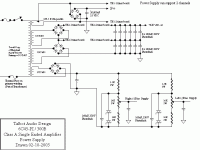
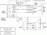
Power Supply Transformer Details
Transformer is from Toroid Corporation of Maryland
Model Number is 401.040 400VA transformer kit, wininding details to follow soon.
Transformer is from Toroid Corporation of Maryland
Model Number is 401.040 400VA transformer kit, wininding details to follow soon.
Zener Question
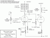
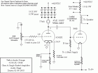
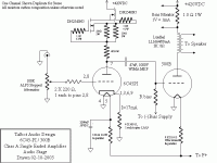
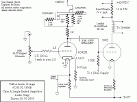
To lower the b+ not to excede the rating on the depletion mode FET. I have also updated the schematic to show the bias monitor for the output tube. Set the output tube bias to 60mA.
To lower the b+ not to excede the rating on the depletion mode FET. I have also updated the schematic to show the bias monitor for the output tube. Set the output tube bias to 60mA.
Re: Zener Question
Zeners are one of the most noisy component in electronics...they produce lots of white noise.
Just one sugestion...
But a resistor will do the same with less noise and increasing the output impedance of the current source...MIKET said:To lower the b+ not to excede the rating on the depletion mode FET.
Zeners are one of the most noisy component in electronics...they produce lots of white noise.
Just one sugestion...
Resistor sub for Zener
I will give it a try and let you know what improvement if any is noted, I will keep you posted. I will try a6K 10W resistor for starters.
I will give it a try and let you know what improvement if any is noted, I will keep you posted. I will try a6K 10W resistor for starters.
Re: Resistor sub for Zener
Good luck and keep in touch!!🙂
Another point in favor of the resistor is that the mosfet have great parasitics capacitances that shunt power suplly noise to the anode of the input tube...and the resistor help to isolate this parasitic path...😉MIKET said:I will give it a try and let you know what improvement if any is noted, I will keep you posted. I will try a6K 10W resistor for starters.
Good luck and keep in touch!!🙂
When you try the dropping resistor also try putting the resistor between the CCS and the plate of the triode. This helps isolate the capacitance of the CCS from the triode.
Are you using a single mosfet CCS or cascading a pair to improve the CCS performance?
Based on shunt capacitance, the performance of 2 cascaded mosfets is only about 180 times better than a single mosfet. 😀 The shunt capacitance of the cascade verison is .177pf verses 32.4pf for the single mosfet. These numbers are for Supertex DN2540 mosfets.
I have a graph of impedance versus frequency and capacitance numbers of the Supertex parts plus several of my designs on my webpage. Look in the CCS performance measurments link. Graphs are at the bottom of the page.
In the "CCS's and signal current controll" link is a schematic for the cascade mosfet circuits. I was calling them cascode but this configuration is not really a cascode. I have an application note from Siliconix that uses cascade as the term for the configuration where the gate of the upper mosfet is referenced to the source of the lower mosfet. I'll be updating the references as time permits
Gary
Gary P's DIY page
Update on CCS
The existing circuit is a single Depletion Mode FET, based on your input and those from others I will try the cascode version Rev 4d found at:
http://home.zonnet.nl/horneman/mosfet.htm
It will be a few days before I can get the soldering iron warmed up but as soon as I can I will give you feedback on the results.
I see you have stabilized the bias voltage. That will cause the bias current in the 300B's to vary a lot with the mains variations. In my opinion it's better to let the bias supply vary with the mains, that will give you a crude compensation.
High voltage zeners drift a lot with temperature as well.
I would also go with a resistor instead of the zeners and have it between the CCS and the plate.
High voltage zeners drift a lot with temperature as well.
I would also go with a resistor instead of the zeners and have it between the CCS and the plate.
Time to optimize
Now everything is working well, next step optimize components.
I am looking at the Mundorf MCap Supreme SILVER/OIL capacaitor to couple the 2 tubes istead of the WIMA MKP. Anyone out there use this cap? They are availible at
http://e-speakers.com/products/mundorf-sup-so.htm
Now everything is working well, next step optimize components.
I am looking at the Mundorf MCap Supreme SILVER/OIL capacaitor to couple the 2 tubes istead of the WIMA MKP. Anyone out there use this cap? They are availible at
http://e-speakers.com/products/mundorf-sup-so.htm
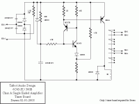
Hi there.......I'm looking.......That power supply is certainly going to kick when the juice is switched on...The 160uF photoflash in the bias circuit is -bit-of-a-slam tactic ? Why such a high value ?
You don't mention the o/p stage bias resistor value....
Parallel zeners ? A zener with the lowest spec "on" voltage will try and rob the others against the spread of the forward dynamic resistance... too unpredictable and not really ideal. Some with higher tolerance may not even be conducting or only just.
It looks if the fets might stew around 5W dissip....I can't quite make out the values on my screen........I'm still working on it...
rich
- Status
- Not open for further replies.
- Home
- Amplifiers
- Tubes / Valves
- Just finished my new 300B amp
