Bas Horneman said:Hi Mike,
I am curious how the DN2540 ccs changed the sound. Better? Same?
Cheers,
Bas
Me too! 🙂
Brian.
Hi there.......Despite your remarks regarding balancing resistors, I presume you ahven't updated the drawing on the stack of 160uF >on 450V B+ ?
For fixed bias op, that 150K bias res seems a touch on the high side.....perhaps not. I haven't used the 300B.
That filament supply....if you notice hum.....post DC regulation could work wonders here and easy to implement..........
What output power are you anticipating ?
rich
For fixed bias op, that 150K bias res seems a touch on the high side.....perhaps not. I haven't used the 300B.
That filament supply....if you notice hum.....post DC regulation could work wonders here and easy to implement..........
What output power are you anticipating ?
rich
Responce to last 2 posts
All testing so far has been with O-Scope and a pair of cheap speakers. It's winter here in Maine so I won't be done my final speakers (Beta12LTA with Fostex FT1H in in TQWT, but more on that later) until spring(Which in Maine starts about May 15th).
All testing so far has been with O-Scope and a pair of cheap speakers. It's winter here in Maine so I won't be done my final speakers (Beta12LTA with Fostex FT1H in in TQWT, but more on that later) until spring(Which in Maine starts about May 15th).
more on previous posts
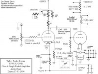
cascaded Depletion mode Fet's were added per the Gary Pimm suggestion, doesn't seem to make a measurable diffence on the scope but if Gary says it will improve the CCS he's the expert so I will defer to his expertise. I started with 300K on the 300B grid and found excessive drift on the bias, so I lowered it to 150K and it has improved the drift. I don't want to go too low and load the 6C45PI signal down. I have also removed the zener diodes in the bias supply to eliminate drift due to line voltage fluctuations.
cascaded Depletion mode Fet's were added per the Gary Pimm suggestion, doesn't seem to make a measurable diffence on the scope but if Gary says it will improve the CCS he's the expert so I will defer to his expertise. I started with 300K on the 300B grid and found excessive drift on the bias, so I lowered it to 150K and it has improved the drift. I don't want to go too low and load the 6C45PI signal down. I have also removed the zener diodes in the bias supply to eliminate drift due to line voltage fluctuations.
more on previous questions
There is almost no ripple on the DC supply, the series resistors are there to eliminate excessive stress on the filiments, as you know cold filiments have a rather low resistance. Prints are up to date as of today but I am willing to tweek this amp as needed. My expected output power is 8 Watts per 300B. This should be fine with my intended 99 dB efficent speakers.
There is almost no ripple on the DC supply, the series resistors are there to eliminate excessive stress on the filiments, as you know cold filiments have a rather low resistance. Prints are up to date as of today but I am willing to tweek this amp as needed. My expected output power is 8 Watts per 300B. This should be fine with my intended 99 dB efficent speakers.
Hi,
If you continue to experience bias drift, try 100K gridleak.
Adjust the value of the coupling cap to the output tubes if you calculated roll of for 150K accordingly.
With 99dB/1m speakers, the amp had better be quiet as a mouse.
Cheers,😉
EDIT: Did you implement a star ground sheme?
I started with 300K on the 300B grid and found excessive drift on the bias, so I lowered it to 150K and it has improved the drift. I don't want to go too low and load the 6C45PI signal down.
If you continue to experience bias drift, try 100K gridleak.
Adjust the value of the coupling cap to the output tubes if you calculated roll of for 150K accordingly.
With 99dB/1m speakers, the amp had better be quiet as a mouse.
Cheers,😉
EDIT: Did you implement a star ground sheme?
Grounding
Star ground used is actually a piece of #10 copper wire that runs the entire length of the amp and is used as the common ground point. I will try adjusting the bias resistor for the 300B grid and let you know of the results.
Star ground used is actually a piece of #10 copper wire that runs the entire length of the amp and is used as the common ground point. I will try adjusting the bias resistor for the 300B grid and let you know of the results.
Star ground used is actually a piece of #10 copper wire that runs the entire length of the amp and is used as the common ground point. I will try adjusting the bias resistor for the 300B grid and let you know of the results.
Thats not a star ground. In a star grounding scheme, all earths go to a single point. What you have is known a s a ground bus.
Star Ground vs. Ground Bus
This could be a very long and fruitless discussion. The important thing is that each item being grounded end up at the ground point seperately to avoid ground loops.
Some say earth some say ground, but they both mean the same thing.
This could be a very long and fruitless discussion. The important thing is that each item being grounded end up at the ground point seperately to avoid ground loops.
Some say earth some say ground, but they both mean the same thing.
Hi,
I agree and very much doubt it has anything to do with your observations.
The reason I asked is just to see whether grounding was done randomly or not.
The buswire should be O.K., if you solved the bias drift problem and want the icing on the cake you can always try proper stargrounding later on.
Cheers,😉
This could be a very long and fruitless discussion.
I agree and very much doubt it has anything to do with your observations.
The reason I asked is just to see whether grounding was done randomly or not.
The buswire should be O.K., if you solved the bias drift problem and want the icing on the cake you can always try proper stargrounding later on.
Cheers,😉
Time to get some Caps
Well today the company anounced we did so well last year we all got a bonus. So now I can afford the best possible caps for the amp.
I'm thinking Mundorf MCap Supreme SILVER/OIL capacaitor but am willing to consider others. Here is a call out to all of you lovers of exotic Caps.
Well today the company anounced we did so well last year we all got a bonus. So now I can afford the best possible caps for the amp.
I'm thinking Mundorf MCap Supreme SILVER/OIL capacaitor but am willing to consider others. Here is a call out to all of you lovers of exotic Caps.
Miket, you might try an interstage transformer ... will best a coupling cap by a substantial margin (much improvement by tying the output tube's grid to ground and reducing grid-current-induced voltage fluctuations). I would otherwise suggest a teflon tin foil capacitor ... ooooh!
Hi,
Asking for trouble, are we?😀
I don't know of anyone that has actually compared everything on the market but here's what I prefer from at least two dozen of brands:
In order of preference and yes, the most expensive ones did come out on top, unfortunately:
- Mundorf PIO Silver foil .
- Jensen PIO Copper foil.
- MIT RTX range (film & foil polystyrene).
- MIT PPFX range(film & foil polypropylene)
- MIT MKP (metallised polypropylene)
-Audyn Cap Zn metallised polyprolyne and zinc foil.
Non-boutique caps:
Siemens EPCOS MKV.
ICEL MKP 1200VDC.
Etc...Didn't bother to induce myself a headache as most others are either too coloured or too veiled to mention.
PSU:
ASC
SOLEN
Other MKP/MKV
Generic PIO.
Cheers,😉
Here is a call out to all of you lovers of exotic Caps.
Asking for trouble, are we?😀
I don't know of anyone that has actually compared everything on the market but here's what I prefer from at least two dozen of brands:
In order of preference and yes, the most expensive ones did come out on top, unfortunately:
- Mundorf PIO Silver foil .
- Jensen PIO Copper foil.
- MIT RTX range (film & foil polystyrene).
- MIT PPFX range(film & foil polypropylene)
- MIT MKP (metallised polypropylene)
-Audyn Cap Zn metallised polyprolyne and zinc foil.
Non-boutique caps:
Siemens EPCOS MKV.
ICEL MKP 1200VDC.
Etc...Didn't bother to induce myself a headache as most others are either too coloured or too veiled to mention.
PSU:
ASC
SOLEN
Other MKP/MKV
Generic PIO.
Cheers,😉
Important Update Schematic Change
Complete schematic can be found at:
http://home.midmaine.com/~talbot/talbot_audio_design/index.htm
Complete schematic can be found at:
http://home.midmaine.com/~talbot/talbot_audio_design/index.htm
Attachments
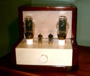
It's done and it sounds great
Schematic Located at:
http://home.midmaine.com/~talbot/talbot_audio_design/index.htm
Latest Mods, regulator for 5V on 300B, Lowered B+ to 400V from 420V lowered ripple by a huge amount.
This is the most quiet tube amp I have ever heard, no hiss no hum the quiet passages are dark as night and it is very clean and dynamic.
- Status
- Not open for further replies.
- Home
- Amplifiers
- Tubes / Valves
- Just finished my new 300B amp